background image

High ef

fi

 ciency heat recovery unit with cooling circuit - 

RHE

 -

27

Selection, installation, use and maintenance manual

GB

TABLE 3  


Voltage 

± 10% the nominal voltage (EN60204)

Frequency 

± 1% frequency in continuous way


± 2% for breve periodo

Room humidity during operation                           from 30% to 95%, without condensate 


or icebild-up (EN60204)

Room humidity during operation   

i

ncluded b5 and +40°C 

(EN60204)

Altitude 

Up to 1000 m s.l.m (EN60204)

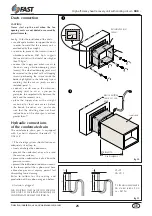
The unit is completely wired in the 
factory and requires the power supply, 
intercepted with inline protections, 
indicated on the unit specification plate 
in order to be started.
The installer should define the power 
supply line based on the length, the 
type of cable, the absorption of the unit 
and the displacement. (TAB.3)
All electrical connections must be in 
accordance with the present standard at 
the moment of installation.

CAUTION:
Refer to the electrical layout supplied 
with the equipment for installation 
needs.

Check that all power cables are 
correctly secured to the terminals 
when switched on for the first time and 
after 30 days of use. Afterwards, check 
the connection of the power cables 
every six months. Slack terminals could 
cause the cables and components to 
overheat.
The electrical wiring and connections 
must be done by  qualified persons in 
accordance with regulations currently 
in force. 

E ve ry   e l e c t r i c a l   u s e r   m u s t   b e 
connected to the system's earthing 
system.

Use the connectors with the earth 
symbol to connect the earthing of the 
unit and possible accessories to the 
earthing of the building.
Respect the installation power supply 
and environment conditions.


Keep the panel and wiring away from 

electric and magnetic fields that could 
disturb, such as inverters, high voltage 
power supply lines,etc.

CAUTION!
Once the connections have been made, 
check that:
all the cables have been correctly 
connected, and that there are no short 
circuits between terminals and the 
terminals and ground. 
the electrical terminals both within 
the electrical panel as well as in the 
terminal board of the compressor are 
secured and that the mobile and fixed 
contacts of the remote control switches 
do not show signs of wear.
Do not block the air intake of the panel.
Never connect or disconnect the 
remote terminal with energised main 
board. 

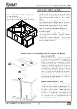
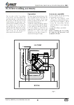
Electrical connections

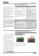
The inverters mounted on the machine 
have the function of keeping the flow 
rate of the fans constant when the unit 
experiences pressure drops (blocked fil-
ters, new accessories installed, etc.). For 
this reason it is possible to use certain 
dip-switches based on the tables shown 
below.
Naturally, before working on the insi-
de of the inverter, you need to have 
carefully read the instructions for use, 
the user manual and the programming 
sheet, and you need to know the ope-
rating modes and the relative settings. 
Access to the inverter and changing 
the settings should always be carried 
out in the absence of supply voltage by 
qualified technical personnel, who are 
knowledgeable of the safety applica-
tions required by the legislation, regu-
lations and standards in force for the 
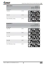
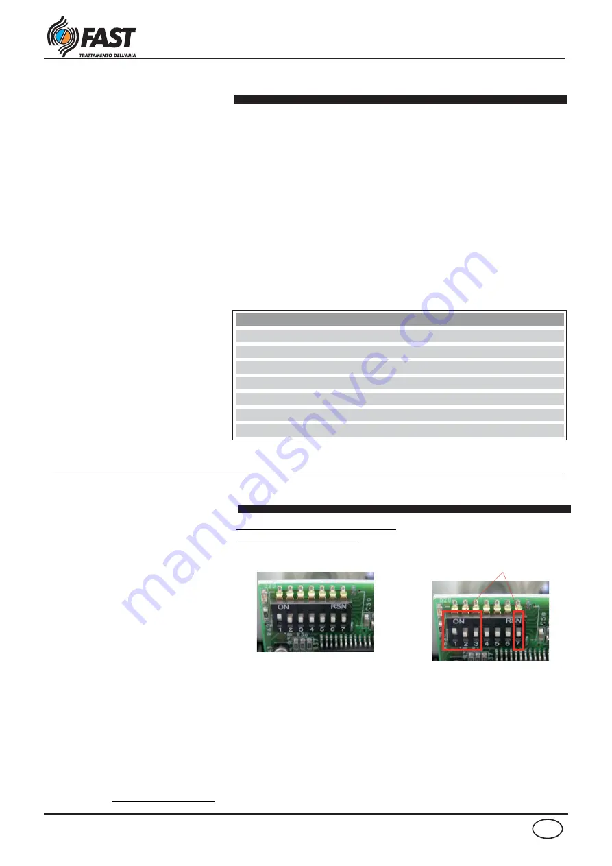
location of the installation. There are 7 
dip-switches: some of them absolutely 

have to remain at their factory settings 
so as not to void the warranty. 

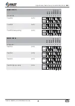
NB: The dip-switches 1, 2, 3 and 7 must 
absolutely stay in the positions indica-
ted by FAST, while 4, 5 and 6 can be 
changed in relation to the desired flow 
rates.

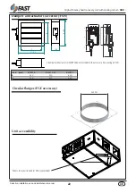
Changing SET fans flow rate 

Positions of the fixed 

dip-switches.

Summary of Contents for RHE 15

Page 1: ...0313 6180505 07 SELECTION USE INSTALLATION AND MAINTENANCE MANUAL HEAT RECOVERY UNITS WITH COOLING CIRCUIT RHE Series GB FAST S p A ISO 9001 2000 Cert n 0882 4...

Page 2: ......

Page 3: ...nter operation 15 Dimensions 16 Accessories dimensions 19 Accessories assembly instructions 21 Instructions for assembling roofs for outside installation 21 Installation and use of the unit 23 Positio...

Page 4: ...ders atten tion concerning risks that can t be avoided or sufficiently limited with the adoption of protection means and measures GENERAL DANGER SIGNS Carefully observe all indications at the side of...

Page 5: ...lings easier with easy accessibility for the maintenance of all internal parts This gives the opportunity also thanks to the management and installation simplicity to satisfy many system requirements...

Page 6: ...s static cross flows recuperator made of aluminium sheets to grant high performances During winter operation the average efficiency is above 80 for the first two sizes and 70 for the last two sizes en...

Page 7: ...ccessory is not compatible with the MBCH MBCX MSS and FBH accessories NB for further information refer to the tables in this manual and to the various accessory kits for compatibility refer to fig 02...

Page 8: ...acity 3 kW 2 8 2 9 3 9 7 0 Available cooling capacity 2 kW 1 8 3 1 3 3 5 4 Recovered heating capacity 3 kW 3 6 10 0 15 3 19 6 Recovered cooling capacity 2 kW 2 2 3 2 4 5 5 8 Refrigerating circuit heat...

Page 9: ...pressure drop at nominal flow rate Pa 7 18 37 37 Heating capacity 1 kW 7 68 10 35 15 56 19 7 Heating capacity 2 kW 2 57 4 04 6 45 7 6 Water flow rate 1 l h 673 906 1363 1725 Water side pressure drop n...

Page 10: ...heat pump operating C 10 10 10 10 Max external temp with heat pump operating C 28 28 28 28 Max internal temp with heat pump operating C 30 30 30 30 Min internal temp with heat pump operating C 14 14 1...

Page 11: ...table to determine the total refrigerating and heating performance based on the outside conditions External air temperature C Key Room air temperature Summer operation 26 C 50 UR fig 04 Heating perfor...

Page 12: ...in the room on the variation of the external conditions The variability of the air flows is that allowed to guarantee that the refrigerating circuit operates correctly Note The following diagrams are...

Page 13: ...ssure drops Pa on the air side based on the flow rate for the MBCH and MSS accessories Fig 08 illustrates the pressure drops kPa water side of the MBCH accessory coil Note The pressure drops illustrat...

Page 14: ...nd maintenance manual GB Refrigerating circuit summer operation KEY CP Compressor BC Condensing coil BE Evaporating coil F Filter RL Liquid receiver PA High pressure probe VIC Inversion valve AP High...

Page 15: ...nd maintenance manual GB Refrigerating circuit winter operation KEY CP Compressor BC Condensing coil BE Evaporating coil F Filter RL Liquid receiver PA High pressure probe VIC Inversion valve AP High...

Page 16: ...c g kg Gx Gy RHE 10 300 700 650 RHE 15 310 740 745 Gx Gy FILTER ACCESSIBILITY CONDENSATE DISCHARGE 1 J UNI 338 CONDENSATE DISCHARGE 1 J UNI 338 FILTER ACCESSIBILITY SUPPLY FAN EXHAUST FAN BY PASS FOR...

Page 17: ...anual GB Weights and c g kg Gx Gy RHE 25 373 1130 920 Gx Gy RHE 25 FILTER ACCESSIBILITY FILTER ACCESSIBILITY CONDENSATE DISCHARGE 1 J UNI 338 CONDENSATE DISCHARGE 1 J UNI 338 BY PASS FOR FREE COOLING...

Page 18: ...tenance manual GB Weights and c g kg Gx Gy RHE 33 410 1365 1145 Gx Gy RHE 33 FILTER ACCESSIBILITY FILTER ACCESSIBILITY CONDENSATE DISCHARGE 1 J UNI 338 CONDENSATE DISCHARGE 1 J UNI 338 BY PASS FOR FRE...

Page 19: ...Modules Mod mm RHE 10 15 25 MSS 1 RHE 33 MSS 2 A 684 846 5 B 684 684 C 574 574 D 500 500 E 59 59 F 59 59 G 16 16 H 718 880 5 I 12 5 12 5 L 342 432 5 M 287 287 N 624 624 A B C Mod mm RHE 10 15 BIT 1 R...

Page 20: ...10 15 25 MBCX 1 2 3 RHE 33 MBCX 2 A 610 772 5 B 574 574 C 359 359 D 718 880 5 E 342 423 F 342 423 G 500 500 H 250 287 I 287 287 L 37 37 M 61 61 N 12 5 12 5 O 110 110 P 78 76 Q 68 71 R 150 150 S 225 2...

Page 21: ...ons for assembling roofs for outside installation The roofs of the base unit are composed of two parts 1 2 one part has an accessible panel 1 for allowing the flat filters to be serviced The two parts...

Page 22: ...l GB Unit accessibility Circular flanges FGE accessory 380 mm Dampers and actuators accessory FCH Mod mm RHE 10 RHE 15 25 RHE 33 B 450 550 600 H 310 410 460 2 dampers with actuators ON OFF 230V are in...

Page 23: ...ust not be used to recover equipment spare parts Any use other than those indicated in this manual may generate hazards and is therefore prohibited Before performing maintenance or cleaning operations...

Page 24: ...supporting brackets for horizontal installation The unit can be fixed by means of fins bars by steel M6 of suitable length blo cked through nuts and washers to sup port brackets assembled to unit it...

Page 25: ...ween the ducts and the recovery unit place the supply duct with a straight section of at least one meter before the bends branches etc and make sure that the ductling does not have inclinations of the...

Page 26: ...the damper B In order to use the free cooling function a duct is required to connect to damper A and another to connect to damper B The two dampers A and B have an opposing function When the outside...

Page 27: ...wiring away from electric and magnetic fields that could disturb such as inverters high voltage power supply lines etc CAUTION Once the connections have been made check that all the cables have been c...

Page 28: ...BLE VARIABLE VARIABLE FIXED DIP SWITCHES 1 2 3 4 5 6 7 Flow 800 m3 h Flow 900 m3 h Flow 1000 factory setting m3 h ON OFF ON OFF ON OFF MODEL RHE 15 FIXED FIXED FIXED VARIABLE VARIABLE VARIABLE FIXED D...

Page 29: ...IXED VARIABLE VARIABLE VARIABLE FIXED DIP SWITCHES 1 2 3 4 5 6 7 Flow 2050 m3 h Flow 2300 m3 h Flow 2550 factory setting m3 h ON OFF ON OFF ON OFF MODEL RHE 33 FIXED FIXED FIXED VARIABLE VARIABLE VARI...

Page 30: ...n be washed with cold water To disassemble the filters remove the inspection panel with knobs remove the filters clean the filters replace all parts in reverse order Condensate drain pan Dirt can hoar...

Page 31: ...ded for disposal Decommissioning Disconnect the unit All decommissioning operations must be performed by authorized personnel in accordance with the national legislation in force in the country where...

Page 32: ...ction or contacts open Check the voltage and close the contact Thermostat does not System at temperature no respond request check the setting and the functioning Safety device does not See point 9 and...

Page 33: ...refrigerant 16 Evaporator coil Lack of refrigerant in the circuit Check for leaks and eliminate them before bubbles visible in the indicator roofping up with refrigerant Thermostatic expansion valve o...

Page 34: ...NOTE...

Page 35: ......

Page 36: ...Tel 39 0429 806311 Fax 0429 806340 E mail info fastaer com http www fastaer com 0313 6180505 07 Technical data shown in this booklet are not binding FAST S p A shall have the right to introduce at an...

Reviews: