
High ef
fi
ciency heat recovery unit with cooling circuit -
RHE
-
30
Selection, installation, use and maintenance manual
GB
Checks during operation
The air flow rate values must not be
lower than 15% of the nominal values
indicated in the technical specifications
table. If an electrical resistance is
present, check the cut-in by measuring
its electrical absorption.
Requirements for R407C
gas
The circuit chillers that work on
R407C cooling gas require particular
a t t e n t i o n d u r i n g a s s e m b ly a n d
maintenance, to prevent operating
faults.
Therefore it is necessary to:
- Avoid refilling with oil different from
the one specified and already used in
the compressor.
- If there are gas leaks causing the unit
to be even partially empty, do not
refill with refrigerant, but empty the
unit completely and refill it with the
foreseen amount.
-
In the event of replacement of one of
the refrigerating circuit parts, do not
leave the circuit open for more than
15 minutes.
-
In particular, in the event of
replacing the compressor, complete
the installation within the above-
mentioned time after the rubber
plugs have been removed.
- When empty, do not switch on the
compressor; do not compress the air
within the compressor.
- When using R407C gas bottles,
it is recommended to take care of
the maximum number of drawings
permitted in order to guarantee the
correct ratio of components of the
R407C gas.
Refrigerant charge
For data relared to refrigerant gas
quantity R410A to charge, please refer
to the identification plate on the unit.
Unit maintenance
CAUTION !
•
During the maintenance phase, wear
proper individual protection devices
(IPD)
•
Before performing maintenance and/
or cleaning operations on the unit,
make sure the unit is disconnected
from the power supply and that it can
not be turned back on without the
knowledge of the person performing
maintenance, and that the heat
exchanger coils are not working.
•
During maintenance the weight of the
inspection panelling could hinder the
work.
The RHE series recovery units have
been designed to require very little
maintenance and to make every
operation easy. Some simple pieces
of advice follow for the proper
maintenance of the unit.
Filters
Filter cleaning is imperative to maintain
high air quality in the room. The
synthetic filters installed in the RHE unit
can be regenerated with compressed air
or can be washed with cold water. To
disassemble the filters:
• remove the inspection panel with
knobs;
• remove the filters;
• clean the filters;
• replace all parts in reverse order.
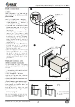
Condensate drain pan
Dirt can hoard up in the condensate drain
pan. You are therefore recommended to
clean the pan regularly and check that the
discharge pipe is not clogged.
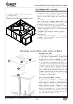
To remove the condensate drain pan of the
heat recovery unit.
If the unit is placed in the ceiling:
• remove all bottom panels;
• disassemble the cross bar;
•disconnect the pan from the condensate
drain pipes;
• disassemble the pan supporting brackets;
• clean the pan;
• replace all parts in reverse order.
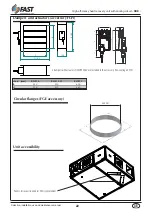
If the unit is placed on the ground:
• remove all above panels;
Before the start-up
Before start-up check that:
– the system has been charged and the
air has been blown out;
– the electrical connections have been
made correctly;
– the line voltage is within the permitted
allowance (±10% of the rated value);
Unit start-up
For detailed information regarding
the operating parameter settings and
all other machine or control card
operations, please refer to the user
manual.
CAUTION!
Make sure that all the instructions have
been complied with before carrying
out the commissioning checks.
Before the first start-up of the heat
recovery unit check the following
points:
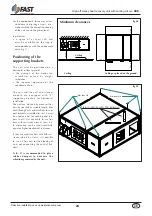
• the exact positioning of the panels
in correspondence with the motor
ventilating assembly that require
opening by means of a screw-driver;
• the fixing of the unit to the wall;
• the earthing of the unit to the
buildings earth system;
• the connection to the ducts;
• the condensate drain connection to
the trap;
• the insulation of the tubes to the coils;
• the ground wires of the electrical
components;
• the absence of air in the water coils.
In particular check that:
• the electrical connection has been
performed correctly and that all
terminals have been sufficiently
tightened;
• the voltage on the terminals is 230
V ± 10% (for units with single-phase
power) or 400 V ± 10% (for units with
three-phase power):
If the voltage is subject to frequent
ch a n g e , c o n t a c t o u r Te ch n i c a l
department in order to select the
necessary protection;
• there are no leaks of refrigerant
through the use of a leak detector.
CAUTION!
Before start-up, check that all the
panels of the unit are in place and
secured with the screws.
WARNING!
If, at the time of the first start, the
compressor don’ t start, the cause can
be attributed to a wrong wiring of the
sequence of the phases L1-L2-L3 or
to the interruption of one of them,
resulting in the intervention of the
relay of the phase sequence.