High ef
fi
ciency heat recovery unit with cooling circuit -
RHE
-
24
Selection, installation, use and maintenance manual
GB
for the components (three-way valves,
condensate drainage traps, etc.)
without which the correct functioning
of the unit can not be guaranteed;
In particular:
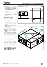
• a space of at least 200 mm
must be available for the trap in
correspondence with the condensate
drain (fig. 11).
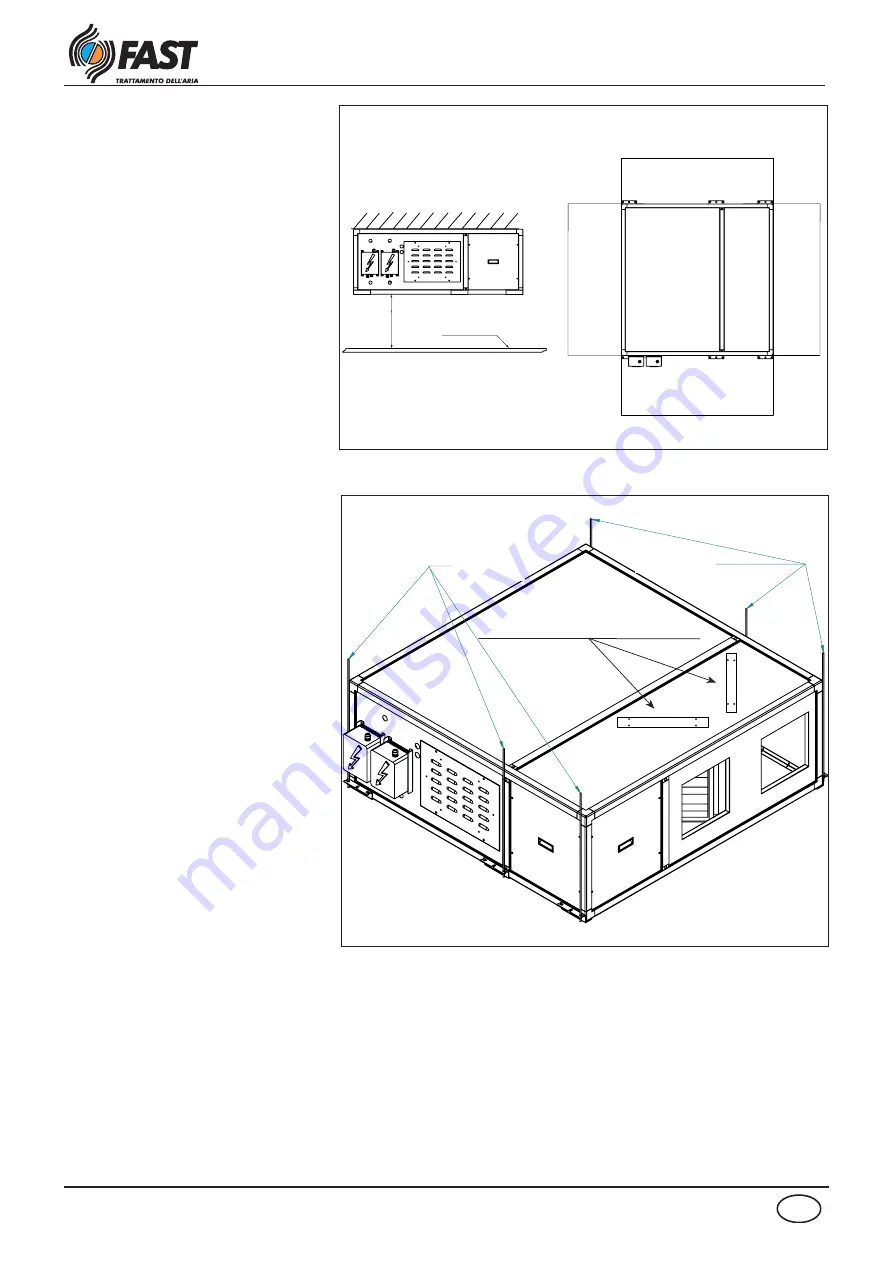
Positioning of the
supporting brackets
The unit must be positioned on a
horizontal surface to avoid:
• the damage of the motor fan
a s s e m b l i e s c a u s e d by w e i g h t
imbalance
• the incorrect operation of the
condensate drain.
The unit and the coil and silencer
m o d u l e a r e e q u i p p e d w i t h " L "
supporting brackets for horizontal
installation.
The unit can be fixed by means of fins
bars by steel M6 of suitable length, blo-
cked through nuts and
washers
to sup-
port brackets assembled to unit; it must
be used one bar for each bracket (n.6
bars in all). It is advisable to use fins
bars with resistancy class at least 4.6.
In alternative, can be used tiranti with
equal or higher mechanical resistency.
If they are used fins bars with hifh resi-
stancy (class 8.8 at least), it is possible
to use n.4 fins bars for the blocking of
unit, not connecting the central bra-
ckets.
N.B.: It is recommended to place
rubber dampers to decrease the
vibrations generated by the unit.
fig.08
fig.09
F
INS
BARS
M6
F
INS
BARS
M6
800 mm
200 mm
200 mm
200 mm
800 mm
Minimum clearances
Panels for inspection and/or filters replacement
Ceiling
Ceiling
Ceiling or placed on the ground


