


High ef
fi
ciency heat recovery unit with cooling circuit -
RHE
-
31
Selection, installation, use and maintenance manual
GB
• disassemble the cross bar;
• disconnect the pan from the
condensate drain pipes;
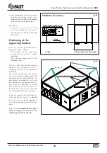
• disassemble the pan supporting
brackets;
• clean the pan;
• replace all parts in reverse order.
In order to access the condensate drain
pan on the coil module, detach the
module from the unit and disassemble it.
Heat recovery unit
The heat recovery unit can be cleaned
with a jet of compressed air or cold
water. To disassemble the heat recovery
unit:
• remove the condensate drain pan (if
the unit is placed in the ceiling);
• remove the heat recovery unit
supporting brackets;
• clean the heat recovery unit;
• replace all parts in reverse order.
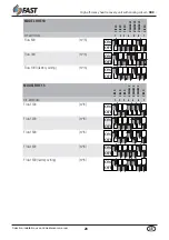
COMPONENT
OPERATION
FREQUENCY
Filters
cleanliness control
twice a week
Heat exchanger coil coil claning control each year
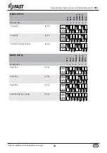
Condensate pan
cleanliness control
each year
Heat recovery unit
coil claning control
each year
The table indicates the maintenance operations
concerning each component, indicating the
type of check to perform and when it should be
performed.
The frequency is approximate and varies
depending on the working and environmental
conditions in which the heat recovery unit
operates.
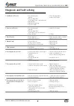
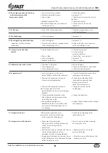
Disposal
All units are checked and tested at
the factory before shipment, however,
during operation an anomaly or failure
can occur.
BE SURE TO RESET AN ALARM ONLY
AFTER YOU HAVE REMOVED THE
CAUSE OF THE FAULT; REPEATED
RESET MAY RESULT IN IRREVOCABLE
DAMAGE TO THE UNIT.
At the end of their operating life,
the RHE units must be disposed of
according to the present laws.
The main components including the
unit of the URFC series are made from:
• Galvanised sheet steel (panels ,
condensate drain pan, fans);
• aluminium sheet metal (coil fins,
dampers, electrical motor casing);
• copper (coil tubes, electric motor
winding );
• polyurethane foam (insulation of the
sandwich panels);
• rock wool (silencers);
• the cooling gas is recuperated by
specialised personnel and forwarded
to the disposal centre;
• the compressor oil is also recovered
and forwarded for disposal.
Decommissioning
Disconnect the unit
All decommissioning operations
must be performed by authorized
personnel in accordance with the
national legislation in force in the
country where the unit is located.
•
Avoid spills or leaks into the envi-
ronment.
•
Before disconnecting the machine
please recover:
•
the refrigerant gas;
•
Glycol mixture in the hydraulic
circuit;
•
the compressor lubricating oil.
Before decommissioning the machi-
ne can be stored outdoors, provi-
ding that it has the electrical box,
refrigerant circuit and hydraulic cir-
cuit intact and closed.
Disposal, recovery and re-
cycling
The frame and components, if unu-
sable, should be taken apart and sor-
ted by type, especially copper and
aluminum that are present in large
quantities in the machine.
All materials must be recovered or
disposed in accordance with natio-
nal regulations.
RAEE Directive (only UE)
•
The RAEE Directive requires that
the disposal and recycling of elec-
trical and electronic equipment
must be handled through a special
collection, in appropriate centers,
separate from that used for the di-
sposal of mixed urban waste.
•
The user has the obligation not to
dispose of the equipment at the end
of the useful life as municipal waste,
but to send it to a special collection
center.
•
The units covered by the RAEE Di-
rective are marked with the symbol
shown above.
•
The potential effects on the envi-
ronment and human health are de-
tailed in this manual.
•
Additional information can be
obtained from the manufacturer.
Fans-motor assembly
The fans motor assembly needs to be
checked to see how clean the rotor is,
whether there is corrosion or damage,
and whether there are abnormal noises.
If necessary disassemble the motor fan
assembly as follows:
• remove all inspection panels;
• disconnect the power supply cable;
• unscrew the four screws that hold
each of the motor fan assemblies to the
frame;
• check the motor fan assemblies and
replace them if necessary;
• replace all parts in reverse order.
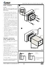
Heat exchanger coils
To maintain an efficient heat exchange
the coils must be cleaned with a jet of
compressed air and the circuit (water
coil) must be free from air.
To access the heat exchanger coil of the
MBC accessory, disconnect the module
from the unit and disassemble it .


