


High ef
fi
ciency heat recovery unit with cooling circuit -
RHE
-
32
Selection, installation, use and maintenance manual
GB
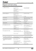
Diagnosis and fault solving
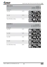
1. Insufficient air flow rate
• Fans rotation speed
• Clean the components
too low
increase the fan speed
• Pressure drop of the
distribution system underestimated
• Blocked filters
• Blocked intake grating
• Coil incrustation
2. Excessive air flow rate
• Fans rotation speed
• reduce the fan speed
too high
• Pressure drop of the
distribution system overestimated
• Filters not fitted
• Fit filters
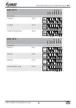
3. No air flow rate
• Power supply off
• Make sure power supply is available
• Electric motor burnt out
• Replace the electric motor
4. Abnormal noise
• Excessive flow rate
• Reduce flow rate
• Bearings worn or defective
• Replace bearings
• Foreign objects on the fan blades
• Clean blades
5. Water movement
• Trap Blocked
• Clean trap
• No trap or incorrectly carried out
• Use an adequate trap
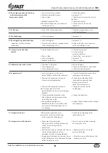
6. The compressor does not start
• Defective connection or contacts open
• Check the voltage and close the contact
• Thermostat does not
• System at temperature, no
respond
request; check the setting and the
functioning
• Safety device does not
• See point 9) and 10)
respond
• Defective compressor
• Replace compressor
7. The compressor does not start
• Compressor burnt out or seized
• Replace compressor
•
Compressor remote control switch de-energised
• Check the voltage across
the operating time of the protection;
automatic compressor shutdown
• Power circuit open
• Check why the protection cut in
compressor; automatic shutdown
8. The compressor starts and then sroofs
• Defective compressor remote control switch • Check and if necessary replace it
• Defective compressor
• Check and if necessary replace it
9. The compressor does not start due to
•Pressure switch out or order
• Check and replace
the intervention of the high pressure
• Excessive refrigerant
• Discharge excess gas
switch
• Presence of incondensable gas
• Refill the circuit after having
in the refrigerating circuit
discharged and placed in vacuum.
• The condensate coil is not sufficiently
• (See point 1)
covered in air
• Blocked refrigerant filter
• Check and replace


