background image

High ef

fi

 ciency heat recovery unit with cooling circuit - 

RHE

 -

33

Selection, installation, use and maintenance manual

GB

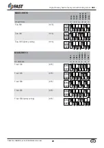
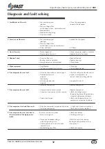
10. The compressor does not start due 


•  Pressure switch out of order  

• Check and replace 


to the intervention of the  


•  Machine completely empty  

• See point 11)


low pressure switch


•  Poor air flow  

• Check the air duct and the state of  


the filters.


•  Blocked refrigerant filter 

• Check and replace


•The thermal expansion valve does not  

• Check, clean or if necessary 


  function correctly 

  replace it.

11. Lack of gas 


•  Leak in the refrigerating circuit  

• Check the refrigerating circuit 


  with a leak detector 
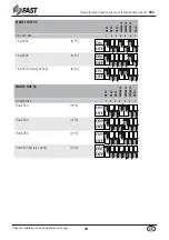
12. Hot liquid pipe 


•  Lack of refrigerant  

• See point 11)

13. The refrigerating circuit functions 


•  Lack of refrigerant  

• See point 11)

    correctly but with insufficient   

•  Presence of humidity or incondensable 

• Replace the filter and if necessary 

    proficiency  

  in the refrigerating circuit  

  drain and refill the circuit 

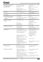
14. Compressor suction tube 


• Thermal expansion valve  

• Check the valve and 


frosted


if it is not working 


  correctly replace it 


•  Poor air flow  

• Check filters, fans and ducts.


•  Lack of refrigerant  

• See point 11)


•  Blocked liquid filter  

• Clean or replace 

15. Abnormal noise in the system 


•  Vibrations in the pipes  

• Secure the pipes


•  Noisy compressor  

• Check electrical phases connection 


•  Noisy thermostatic valve  

• Check and add refrigerant 

16. Evaporator coil 


•  Lack of refrigerant in the circuit:  

• Check for leaks and eliminate them  


  before bubbles visible in the indicator. 

  roofping up with refrigerant.


•  Thermostatic expansion valve over . 

• Reduce the overheating of the 


  closed: suction pipe too hot   

  thermostatic expansion valve    


 turn the valve stem and 


  check the suction pressure . 


•  Thermostatic expansion valve over . 

• Change the valve or free the  


closed: expansion valve bulb   

   control pipe.


  partially blocked or pressure intake pipe  


  blocked 


•  Filter-drier blocked: bubbles in the   

• Change the filter-drier.


  flow indicator and liquid pipe colder 


  at the filter drier outlet  


•  The manifold feed pipes are  

• Remove the obstruction; clean or change 


  blocked or oil has accumulated in the  

  the evaporator.


  coil: not all of the evaporator circuits 


  are working  

17. Compressor too hot 


•Thermostatic expansion valve  

• Reduce the overheating of the 


over closed: excessive overheating  

  thermostatic valve 


  of the evaporator discharge gas 

18. Compressor to cold and noisy 


•  Expansion valve over open:  

• Measure and reset the overheating 


  the system works with the overheating  

  by closing the valve 


  to low  (return of liquid to the 


  compressor). 


•  Thermostatic valve out of order: the stem or   • Replace the valve or free the 


  the seat of the expansion valve is  

  pressure inlet pipe 


  corroded. Pressure inlet pipe blocked.


• Foreign objects between the stem and the seat   • Clean the stem and the holes of the 


  of the thermostatic valve: abnormal function     thermostatic valve 


  of the thermostatic valve 

Summary of Contents for RHE Series

Page 1: ...0313 6180505 07 SELECTION USE INSTALLATION AND MAINTENANCE MANUAL HEAT RECOVERY UNITS WITH COOLING CIRCUIT RHE Series GB FAST S p A ISO 9001 2000 Cert n 0882 4...

Page 2: ......

Page 3: ...nter operation 15 Dimensions 16 Accessories dimensions 19 Accessories assembly instructions 21 Instructions for assembling roofs for outside installation 21 Installation and use of the unit 23 Positio...

Page 4: ...ders atten tion concerning risks that can t be avoided or sufficiently limited with the adoption of protection means and measures GENERAL DANGER SIGNS Carefully observe all indications at the side of...

Page 5: ...lings easier with easy accessibility for the maintenance of all internal parts This gives the opportunity also thanks to the management and installation simplicity to satisfy many system requirements...

Page 6: ...s static cross flows recuperator made of aluminium sheets to grant high performances During winter operation the average efficiency is above 80 for the first two sizes and 70 for the last two sizes en...

Page 7: ...ccessory is not compatible with the MBCH MBCX MSS and FBH accessories NB for further information refer to the tables in this manual and to the various accessory kits for compatibility refer to fig 02...

Page 8: ...acity 3 kW 2 8 2 9 3 9 7 0 Available cooling capacity 2 kW 1 8 3 1 3 3 5 4 Recovered heating capacity 3 kW 3 6 10 0 15 3 19 6 Recovered cooling capacity 2 kW 2 2 3 2 4 5 5 8 Refrigerating circuit heat...

Page 9: ...pressure drop at nominal flow rate Pa 7 18 37 37 Heating capacity 1 kW 7 68 10 35 15 56 19 7 Heating capacity 2 kW 2 57 4 04 6 45 7 6 Water flow rate 1 l h 673 906 1363 1725 Water side pressure drop n...

Page 10: ...heat pump operating C 10 10 10 10 Max external temp with heat pump operating C 28 28 28 28 Max internal temp with heat pump operating C 30 30 30 30 Min internal temp with heat pump operating C 14 14 1...

Page 11: ...table to determine the total refrigerating and heating performance based on the outside conditions External air temperature C Key Room air temperature Summer operation 26 C 50 UR fig 04 Heating perfor...

Page 12: ...in the room on the variation of the external conditions The variability of the air flows is that allowed to guarantee that the refrigerating circuit operates correctly Note The following diagrams are...

Page 13: ...ssure drops Pa on the air side based on the flow rate for the MBCH and MSS accessories Fig 08 illustrates the pressure drops kPa water side of the MBCH accessory coil Note The pressure drops illustrat...

Page 14: ...nd maintenance manual GB Refrigerating circuit summer operation KEY CP Compressor BC Condensing coil BE Evaporating coil F Filter RL Liquid receiver PA High pressure probe VIC Inversion valve AP High...

Page 15: ...nd maintenance manual GB Refrigerating circuit winter operation KEY CP Compressor BC Condensing coil BE Evaporating coil F Filter RL Liquid receiver PA High pressure probe VIC Inversion valve AP High...

Page 16: ...c g kg Gx Gy RHE 10 300 700 650 RHE 15 310 740 745 Gx Gy FILTER ACCESSIBILITY CONDENSATE DISCHARGE 1 J UNI 338 CONDENSATE DISCHARGE 1 J UNI 338 FILTER ACCESSIBILITY SUPPLY FAN EXHAUST FAN BY PASS FOR...

Page 17: ...anual GB Weights and c g kg Gx Gy RHE 25 373 1130 920 Gx Gy RHE 25 FILTER ACCESSIBILITY FILTER ACCESSIBILITY CONDENSATE DISCHARGE 1 J UNI 338 CONDENSATE DISCHARGE 1 J UNI 338 BY PASS FOR FREE COOLING...

Page 18: ...tenance manual GB Weights and c g kg Gx Gy RHE 33 410 1365 1145 Gx Gy RHE 33 FILTER ACCESSIBILITY FILTER ACCESSIBILITY CONDENSATE DISCHARGE 1 J UNI 338 CONDENSATE DISCHARGE 1 J UNI 338 BY PASS FOR FRE...

Page 19: ...Modules Mod mm RHE 10 15 25 MSS 1 RHE 33 MSS 2 A 684 846 5 B 684 684 C 574 574 D 500 500 E 59 59 F 59 59 G 16 16 H 718 880 5 I 12 5 12 5 L 342 432 5 M 287 287 N 624 624 A B C Mod mm RHE 10 15 BIT 1 R...

Page 20: ...10 15 25 MBCX 1 2 3 RHE 33 MBCX 2 A 610 772 5 B 574 574 C 359 359 D 718 880 5 E 342 423 F 342 423 G 500 500 H 250 287 I 287 287 L 37 37 M 61 61 N 12 5 12 5 O 110 110 P 78 76 Q 68 71 R 150 150 S 225 2...

Page 21: ...ons for assembling roofs for outside installation The roofs of the base unit are composed of two parts 1 2 one part has an accessible panel 1 for allowing the flat filters to be serviced The two parts...

Page 22: ...l GB Unit accessibility Circular flanges FGE accessory 380 mm Dampers and actuators accessory FCH Mod mm RHE 10 RHE 15 25 RHE 33 B 450 550 600 H 310 410 460 2 dampers with actuators ON OFF 230V are in...

Page 23: ...ust not be used to recover equipment spare parts Any use other than those indicated in this manual may generate hazards and is therefore prohibited Before performing maintenance or cleaning operations...

Page 24: ...supporting brackets for horizontal installation The unit can be fixed by means of fins bars by steel M6 of suitable length blo cked through nuts and washers to sup port brackets assembled to unit it...

Page 25: ...ween the ducts and the recovery unit place the supply duct with a straight section of at least one meter before the bends branches etc and make sure that the ductling does not have inclinations of the...

Page 26: ...the damper B In order to use the free cooling function a duct is required to connect to damper A and another to connect to damper B The two dampers A and B have an opposing function When the outside...

Page 27: ...wiring away from electric and magnetic fields that could disturb such as inverters high voltage power supply lines etc CAUTION Once the connections have been made check that all the cables have been c...

Page 28: ...BLE VARIABLE VARIABLE FIXED DIP SWITCHES 1 2 3 4 5 6 7 Flow 800 m3 h Flow 900 m3 h Flow 1000 factory setting m3 h ON OFF ON OFF ON OFF MODEL RHE 15 FIXED FIXED FIXED VARIABLE VARIABLE VARIABLE FIXED D...

Page 29: ...IXED VARIABLE VARIABLE VARIABLE FIXED DIP SWITCHES 1 2 3 4 5 6 7 Flow 2050 m3 h Flow 2300 m3 h Flow 2550 factory setting m3 h ON OFF ON OFF ON OFF MODEL RHE 33 FIXED FIXED FIXED VARIABLE VARIABLE VARI...

Page 30: ...n be washed with cold water To disassemble the filters remove the inspection panel with knobs remove the filters clean the filters replace all parts in reverse order Condensate drain pan Dirt can hoar...

Page 31: ...ded for disposal Decommissioning Disconnect the unit All decommissioning operations must be performed by authorized personnel in accordance with the national legislation in force in the country where...

Page 32: ...ction or contacts open Check the voltage and close the contact Thermostat does not System at temperature no respond request check the setting and the functioning Safety device does not See point 9 and...

Page 33: ...refrigerant 16 Evaporator coil Lack of refrigerant in the circuit Check for leaks and eliminate them before bubbles visible in the indicator roofping up with refrigerant Thermostatic expansion valve o...

Page 34: ...NOTE...

Page 35: ......

Page 36: ...Tel 39 0429 806311 Fax 0429 806340 E mail info fastaer com http www fastaer com 0313 6180505 07 Technical data shown in this booklet are not binding FAST S p A shall have the right to introduce at an...

Reviews: