High ef
fi
ciency heat recovery unit with cooling circuit -
RHE
-
6
Selection, installation, use and maintenance manual
GB
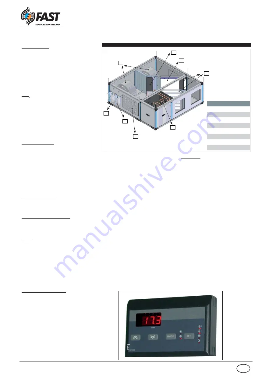
Description of the components
Panels and frame
:
The frame is made up of 25 mm thick
galvanised self-supporting sandwich panels
with injected polyurethane insulation (
density of 42 kg/m
3
) and nylon reinforced
corners with glass fi bre. The construction
of the casing simplifi es installation and
maintenance.
Fans:
They are centrifugal fans with forward-
curved blades and with directly connected
motor. The 230V - 50 Hz single-phase motor
has one speed. The airfl ow in case of pressure
drops changes of internal components
(clogging fi lters) and distribution system
remains costant.
Refrigerating circuit
This is a highly effi cient and silent heat
pump with scroll or rotative compressor
operating with refrigerant R410A (according
to sizes), four-way valve for cycle inversion,
evaporating coil, safety valve, condensing
coil, liquid receiver, thermostatic valve,
liquid light , high/low pressure switch and by
pass valve (for little sizes).
Condensate drain pan:
made of aluminium alloy, removable and
with double discharge.
Evaporating/condensating coil:
with cupper grooved tube and high effi ciency
aluminium fi ns.
Filters:
these are cell undulated type placed before
the recovery unit on the supply and return
airfl ow. The standard fi lters are class G4 type
in accordance with classifi cation UNI EN
779 with weighted effi ciency of 90%. They
are 48 mm thick and are easily removable
from the top or bottom of the unit for to do
the cleaning or replacement.
Dirty fi lters pressure switch:
A differential pressure switch is present, pla-
ced close to the electronic controllers, for the
detection of the supply fi lter clogging. The
interventation value can be set. The pressure
switch includes clean contacts (NA, NC) to
remote the alarm.
Heat recovery unit:
This is static cross fl ows recuperator
made of aluminium sheets to grant high
performances. During winter operation, the
average effi ciency is above 80% for the fi rst
two sizes and 70% for the last two sizes,
ensuring fi rst-class energy recovery from the
air expelled from the room.
Support brackets
:
They allow the unit to be rapidly and securely
fi xed to the false ceiling.
Accessibility:
The heat recovery, the condensate tank, fans
and fi lters are removable from the bottom,
removing the two lower panels (if the unit
is hanging), the same can be easily removed
from the air by removing the two top panels
(if units is on the ground). The inspection
of the electrical panel and the circuit is
guaranteed by side panels. For the inspection
of the fi lters, in both the cabinet and the fl oor
version, you can disassemble the openings
on the top and bottom panels are fastened
with fl yers.
Regulation
The unit is equipped with an electrical panel
with power and regulation section (including
the three-way valve for the additional hot
water coil and related servomotor), aimed
at guaranteeing the management of all
refrigerating circuit functions. Also present:
NTC temperature probe on the internal air
recovery, external air temperature probe,
pressure switch on the supply fi lter.
With the free-cooling accessory are supplied
dampers and servomotors.
A remote control terminal is also supplied
for the automatic management of the unit,
remotable up to 150 meter (cable not supplied).
The unit is equipped for the management of
a luminous sign (230V) which switches on in
case of generic alarm or unit OFF, in conformity
with the norms in force for rooms for smokers.
The following operations can be performed on
the microprocessor: switching on and off of the
unit, summer/winter changeover, setting of set-
point parameters, reading of room temperature.
N.B. For further information refer to
the user manual.
Key
1
Cooling circuit
2
Electric board
3
Centrifugal fan
4
G4 Filter
5
Heat recovery unit
6
Exchange coil
7
Condensate discharge
8
Fans inverter
RHE 10-15
1
2
8
7
3
6
5
4


