Unità roof-top small •
Roof-top small units
-
RTS
-
0605-6180610-rev. 1
Manuale di selezione e installazione
19
GB
Selection and installation manual
I
0,8
1
0,85
0,9
0,95
1,05
1,1
1,15
1,2
Ca
0,5
0,6
0,7
0,8
0,9
1
1,1
1,2
-8
-6
-4
-2
0
2
4
6
8
10
12
14
16
°C
Ct
Te = 16 °C
Te = 20 °C
Te = 24 °C
Te = 20 °C
Te = 24 °C
Te = 16 °C
P
t [kW
]
P
a
[kW
]
Aria esterna b.s. • d.b. External air
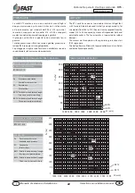
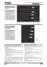
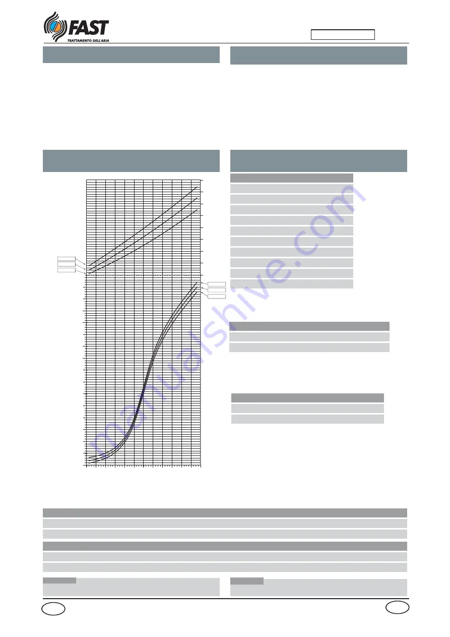
La potenza termica resa e la potenza elettrica assorbita in
condizioni diverse da quelle nominali si ottengono molti-
plicando i valori nominali (Pt, Pa) per i rispettivi coefficienti
correttivi (Ct, Ca).
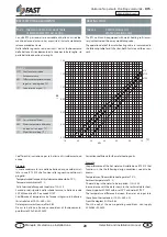
Il diagramma seguente consente di ricavare i coefficienti
correttivi; in corrispondenza di ciascuna curva è riportata la
temperatura ambiente esterna a bulbo secco con umudità
relativa variabile, secondo i dati riportati nella tabella qui
sotto riportata.
Le rese si intendono al netto dei cicli di sbrinamento.
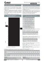
LEGENDA • KEY
Pt
Potenza termica • Cooling Capacity
Pa
Potenza assorbita escluso ventilatore
Absorbed power fan excluded
Ct
Coefficiente correttivo della Potenza termica
Corrective coefficient for cooling capacity
Ca
Coefficiente correttivo Potenza assorbita
Corrective coefficient for heanting capacity
b.s.
Bulbo secco • Dry bulb
Te
Temperatura aria da trattare b.s.
d.b. temperature of the air to be treated
Temp. in ascissa
°C
-8
-6
-4
-2
0
2
4
6
8
10
12
14
16
Temp. B.S.
°C
-8
-6
-4
-2
0
2
4
6
8
10
12
14
16
Umid. Rel.
%
90
90
85
80
75
75
70
70
70
65
65
65
65
ATTENZIONE Nel funzionamento a pompa di calore non sono con-
sentite riduzioni di portata d'aria dell'unità esterna.
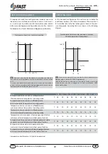
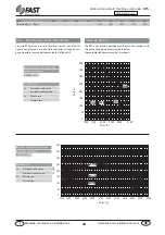
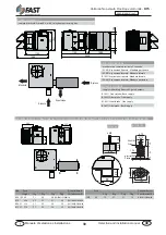
Variazione delle rese totali sulle unità RTS al variare dell'umidità relativa
mantenendo costante la temperatura a bulbo secco:
Variation of the total performances on the RTS units as the relative
humidity varies maintaining the dry bulb temperature constant
Variazione delle rese sensibili sulle unità RTS al variare dell'umidità
relativa mantenendo costante la temperatura a bulbo secco:
Variations of the sensible capacities on the RTS units as the relative
humidity varies keeping the dry bulb temperature constant:
Esempio: se RTS022F dalla scheda tecnica rende a 27°C e 50% U.R.:
pot. frig. tot. 22,0 kW e pot. frig. Sens. 16,5 kW;
Allora a 27°C e 40% U.R. rende rispettivamente: 22,0x0,94=20,7 kW e
16,5x1,11=18,3 kW.
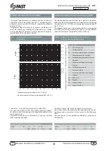
Nella tabella di resa in pompa di calore le ascisse riportano una temperatura la quale fa riferimento alla seguente tabella
In the heat pump performance table the y-axis shows a temperature that refers to the following table
POTENZA TERMICA E ASSORBITA
TAV2 COEFFICIENTE
POTENZA
TERMICA
E ASSORBITA PER VERSIONI H
The heating capacity and the absorbed electric power in
conditions either than the nominal ones, can be obtained by
multiplying the nominal values (Pt, Pa) with their respective
correction factors (Ct, Ca).
The following diagram makes it possible to obtain the cor-
rective co-efficients; indicated next to is the outside tem-
perature with dry bulb with variable relative humidity , in
accordance with the data shown in the table below.
Capacities do not include defrosting periods.
THERMAL CAPACITY AND INPUT POWER
TABLE2 CORRECTIVE COEFFICIENTS FOR HEATING
CAPACITY AND ABSORBED POWER FOR H VERSION
WA R N I N G Reductions in the outdoor unit air flow are not permit-
ted in heat pump operation.
Temp. on y axis
°C
-8
-6
-4
-2
0
2
4
6
8
10
12
14
16
Temp. B.S. D.B. Temp. °C
°C
-8
-6
-4
-2
0
2
4
6
8
10
12
14
16
Umid. Rel. Rel. Humid.
%
90
90
85
80
75
75
70
70
70
65
65
65
65
Example: if RTS022F supplies 22,0 kW tot. cooling cap. and 16,5 kW
sensible cool. cap. at 27°C and 50% R.H.;
Then at 27°C and 40% R.H. it will supply respectively: 22,0x0,94=20,7
kW and 16,5x1,11=18,3 kW.
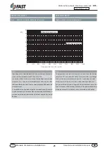
UMIDITÀ RELATIVA VARIABILE • VARIABLE RELATIVE HUMIDITY
U.R.
%
30 40 50 60 70
Coef. corr (°C)
1.23
1.11
1.00
0.89
0.79
UMIDITÀ RELATIVA VARIABILE • VARIABLE RELATIVE HUMIDITY
U.R.
%
30 40 50 60 70
Coef. corr (°C)
0.89
0.94
1.00
1.06
1.12


