


MAINTENANCE AND SERVICE
PAGE 64
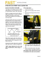
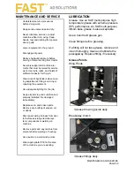
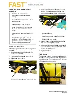
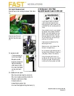
TANK MAINTENANCE AND
SERVICE
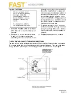
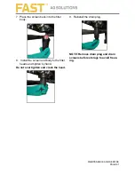
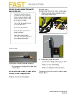
Tank Drain Procedure
Follow this procedure to completely drain
the tank.
1. Spray as much liquid through the
booms as possible.
2. Place a pail under the tank valve.
3. Close the tank valve
.
•Turn valve handle 90° from hose line.
4. Disconnect the hose from the outlet
end of the tank valve and allow the
hose to completely drain into the pail
.
•Loosen clamp
•Carefully remove hose from fitting.
•Drain hose into a pail.
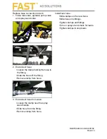
5. Slowly open the tank valve and allow
the tank to completely drain.
6. Once draining is complete, close tank
valve, reconnect the hose to the outlet
end of the tank valve.
7. Tighten clamp.
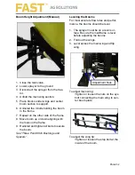
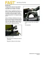
Tank Straps
Tighten the bolt on the strap buckles until
the straps have just started to depress the
top of the tank. The buckles do not have to
be tight against the frame.
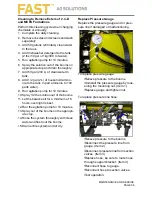
Read the chemical manufactures
warnings and follow instructions
exactly.
Put on the PPE required on the chem-
ical SDS sheet.
Clear bystanders from the area.
Know your working location and how
to seek medical attention in an emer-
gency.
Never put your head or body into the
tank.
Stop tractor engine, place all controls
in neutral, set parking brake, remove
ignition key and wait for all moving
parts to stop before cleaning tank.
Summary of Contents for UT3P
Page 1: ...820037 FAST UT3P Sprayer 9 20 2018 FAST UT3P Sprayer OPERATION AND MAINTENANCE MANUAL...
Page 2: ...820037 FAST UT3P Sprayer 9 20 2018...
Page 5: ...UT3P DELIVERY INSPECTION CHECKLIST PAGE 2 This page intentionally left blank...
Page 19: ...MAJOR COMPONENTS PAGE 16 This page intentionally left blank...
Page 45: ...OPERATION PAGE 42 This page intentionally left blank...
Page 61: ...PAGE 58 This page intentionally left blank...
Page 83: ...820037 9 20 2018...
Page 84: ...820037 9 20 2018...


