www.fastech.co.kr
Control I/O signal
28
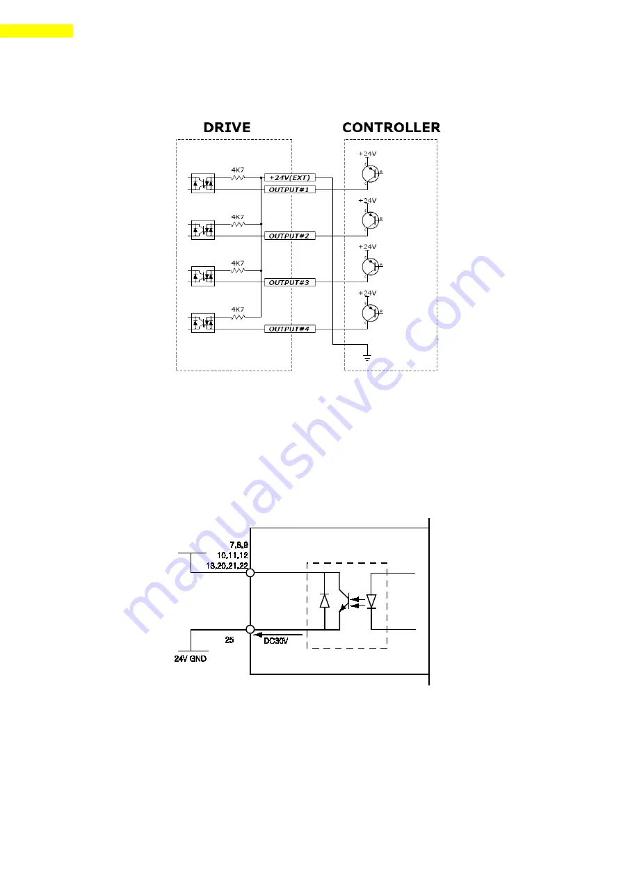
Connect PNP type Input signal
Connect the ‘+24V external’ pin of drive to ‘GND’ of Controller.
2)Output Circuit
Output circuit power should be separately prepared. This may share input circuit power. In
this case, power capacity should add output power capacity to input power capacity.
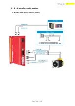
Applied voltage and power capacity in the control output port are as follows.
·Applied voltage
≤
30V
·Electrified current
≤
15mA
Output
Drive inner circuit
Within 15mA
Summary of Contents for Ezi-Servo II Plus-E 20 Series
Page 1: ... Rev 04 User Manual Text ...
Page 10: ...www fastech co kr Specifications size of the Motor 10 ...
Page 11: ...www fastech co kr 11 Specifications size of the Motor 3 2 Motor Size ...
Page 12: ...www fastech co kr Specifications size of the Motor 12 ...
Page 18: ...www fastech co kr Configuration 18 2 86 mm motor drive ...
Page 20: ...www fastech co kr Configuration 20 2 86 mm motor drive ...
Page 74: ...www fastech co kr Appendix 74 12 3 Brake Installed Motor Specifications and Size ...
Page 76: ...www fastech co kr Appendix 76 2 Gearbox for 56mm Motor Specifications ...
Page 77: ...www fastech co kr 3 Gearbox for 60mm Motor Specifications ...
Page 78: ...www fastech co kr Appendix 78 4 Gearbox for 86mm Motor Specifications ...
Page 79: ...www fastech co kr 5 42mm motor size with Gearbox ...
Page 80: ...www fastech co kr Appendix 80 6 56mm motor size with Gearbox ...
Page 81: ...www fastech co kr 7 60mm motor size with Gearbox ...
Page 82: ...www fastech co kr Appendix 82 8 86mm motor size with Gearbox ...


