-72-
Attention
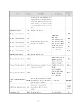
• When setting the speed increasing ratio to 1.00, the speed reduction ratio will
be effective.
• When setting a longer time in the “overload alarm detection time except
when holding a shaft” parameter, an overload status may continue. Repeating
this condition may result in shorter service life of the motor and gearhead.
• If a load exceeding the limited duty region was applied or output shaft was
holded, the “overload alarm detection time except when holding a shaft” is
maximum 5 seconds.
•
Description of I/O signals
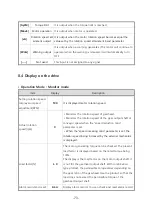
Assignable alternative input functions
Display
Function
Description
[FWd]
FWD
The motor rotates when either FWD input or REV input is set to “ON”.
The motor instantaneous stop when FWD input and REV input is set to
“ON” at the same time.
[rEv]
REV
[P0]
Operation data 0
These signals are used to select the operation data number. 8 speeds c
an be specified by using three opertation datas.
[P1]
Operation data 1
[P2]
Operation data 2
[A.rSt]
Alarm reset
This signal is used to reset the alarm when be operated protection fun
ction.
[E.Err]
External error
When turning this signal OFF, an alarm generates and the motor stops
instantaneously.
[----]
Not used
This input is not assigned to any signal.
Assignable alternative input functions
Display
Function
Description
[SPd]
Rotation speed
For every rotation of the motor, 30 pulses are output
SPEED [RPM] = (SPEED-OUT [Hz] * 60 [Sec]) / 30 [pulses]
[AL.on]
Alarm output
It is output when an alarm is generated (Normally closed)
[AL.ov]
Over voltage alarm
It is output when an alarm is finished (Nomally open)
[OvLd]
Overload alarm
It is output when overload alarm is generated or exceeded
(Normally closed)
Summary of Contents for Ezi-SPEED ESD-30-C
Page 1: ......
Page 9: ...9 2 Characteristics 2 1 Part number...
Page 15: ...15 3 2 Dimensions 30W 60W 120W Drive 200W 400W Drive...
Page 18: ...18 ESM 90 H 120 ESM 104 H 200 ESM 104 H 400...
Page 19: ...19 4 3 Characteristics of motor torque 30W 60W 120W...
Page 20: ...20 200W 400W...
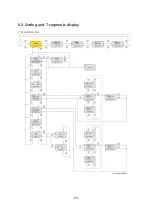
Page 63: ...63 8 2 Setting and 7 segments display 1 Monitor mode...
Page 64: ...64 2 Input Output setting mode...
Page 65: ...65 3 Parameter setting mode 1page...
Page 66: ...66 3 Parameter setting mode 2page...
Page 67: ...67 3 Parameter setting mode 3page...
Page 68: ...68 3 Parameter setting mode 4page...
Page 69: ...69 4 NVM saving mode...


