-91-
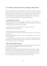
12.2 Installing and wiring method in compliance EMC Directive
This product has been designed and manufactured to be incorporated in equipment. The EMC
Directive requires that your mechanical equipment in which the product is satisfies the applicable
requirements. The final level of comformance of your mechanical equipment to the EMC Directive
will vary depending on the control system equipment used with the other control system with
motor, configuration of electrical parts, wiring, layout, hazard level, and the like. You must be
verified through conducting EMC measures on your mechanical equipment.
• Connecting an AC Line Filter
Install an AC line filter which the customer provides, in the power line in order to prevent the
noise generated within the drive from propagating outside via the AC input line. For AC line filters,
use the products as shown in the below, or an equivalent.
Single-phase 100-120V, 200-240V : 6EMC1 F8127(Corcom), NAC-06-472(Cosel)
Three-phase 200-240V : TAC-06-683(Cosel)
- Install the AC Line Filter as close to drive as possible.
- Use cable clamps and other means to secure the input and output cables firmly to the surface
of the enclosure.
- Connect the ground terminal of the AC Line Filter to the grounding point, using as thick and
short a wire as possible.
- Do not place the AC input cable parallel with the AC line Filter output cable. Parallel placement
will reduce AC line Filter effectiveness if the enclosure’s internal noise is directly coupled to the
power supply cable by means of stray capacitance.
• Note about insulating and wiring
Connect the motor/drive and other peripheral control equipment directly to the grounding point
so as to prevent a potential difference from developing between grounds.
Wire cable as short as possible.
Wire the power lines such as the motor cable and power cable away from the signal cable by
providing a minimum clearance of 100mm between them. If they must cross, do so at a right
angle. Palce AC input cable and output cable of the AC line Filter separately from each other.
Use a connection cable of option when extending the wiring distance between the motor and
drive. The EMC measures are conducted using the FASTECH connection cable.
Summary of Contents for Ezi-SPEED ESD-30-C
Page 1: ......
Page 9: ...9 2 Characteristics 2 1 Part number...
Page 15: ...15 3 2 Dimensions 30W 60W 120W Drive 200W 400W Drive...
Page 18: ...18 ESM 90 H 120 ESM 104 H 200 ESM 104 H 400...
Page 19: ...19 4 3 Characteristics of motor torque 30W 60W 120W...
Page 20: ...20 200W 400W...
Page 63: ...63 8 2 Setting and 7 segments display 1 Monitor mode...
Page 64: ...64 2 Input Output setting mode...
Page 65: ...65 3 Parameter setting mode 1page...
Page 66: ...66 3 Parameter setting mode 2page...
Page 67: ...67 3 Parameter setting mode 3page...
Page 68: ...68 3 Parameter setting mode 4page...
Page 69: ...69 4 NVM saving mode...

