background image


FN ICON CALIBRATION AND REBUILD INSTRUCTIONS 


    Roseville, MN 

     Ph: 1-800-444-2373 
     Fax: 651-645-7390 

     www.fastestinc.com 

                                                             Page 

2

 of 

5

                                                                                                                                                                                                    WP158 Rev C, 12/13/2021  


WIRING DIAGRAM: 


SSR MODULE CALIBRATION (LEVER ONLY): 

Sure Seal™ 

enabled connectors need to be calibrated to each application. 

The FasMate con-

nector retains stored limit(s) even when power is removed. 

Due to the fine sensor resolution 

and variations in seal height, limits may need to be set each time seals are replaced, or the con-
nector is re-built. 

1. 

Rotate the red housing to the desired location and lock it in place with the set screw. 

2. 

NOTE:  If  needed  the  Lever 
version can be backed out one 
full  turn  from  tight.  The  ideal 
position for the red housing is 
tight against the body.


STOP! READ STEPS 3-6 BEFORE STARTING CALIBRATION. 


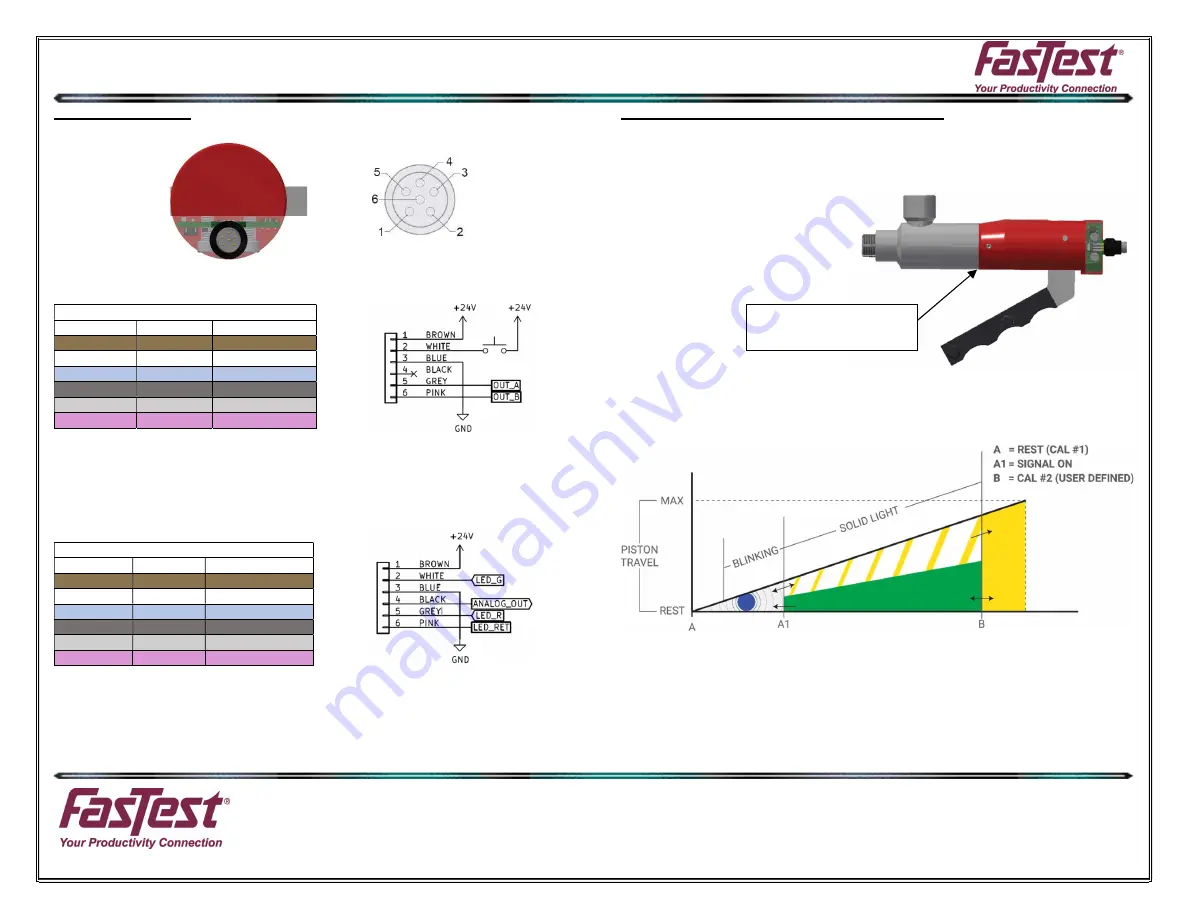
Note: Point A1 is a preset distance from the rest position (A). As the shaft is extended from 
rest, it will begin flashing yellow within the good zone. A good connection is only indicated 
when the shaft retracts from beyond the upper limit (B). If a good connection is made and 
it’s just to the right of Point A1, it could travel through point A1 once test pressure is intro-
duced, and the light will change from green to flashing yellow. Cancel the test, reconnect, 
and try again. 
 

Pinout/Standard M8 Cables 

Pin Number 

Wire Color 

Description 

BROWN 

24 VDC 

WHITE 

CALIBRATION 

BLUE 

GROUND 

BLACK 

NC 

GREY 

SSR CONTROL A 

PINK 

SSR CONTROL B 

Pinout/Standard M8 Cables 

Pin Number 

Wire Color 

Description 

BROWN 

24 VDC 

WHITE 

LED GREEN 

BLUE 

GROUND 

BLACK 

ANALOG OUTPUT 

GREY 

LED RED 

PINK 

LED RETURN 

CV04SSR Pinout 

CV04SSR Wiring Diagram 

CV04ANA Pinout 

CV04ANA Wiring Diagram 

LEVER HOUSING 

TIGHT TO BODY 

Summary of Contents for FN Series

Page 1: ...nts its products against defects of workmanship and or material for 12 months from the date of the sale by FasTest Inc This warranty is void if the product is misused tampered with or used in a manner that is not in accordance with FasTest Inc recommendations and or instructions FasTest Inc is not liable for consequential or other damages including but not limited to loss damage personal injury or...

Page 2: ...STEPS 3 6 BEFORE STARTING CALIBRATION Note Point A1 is a preset distance from the rest position A As the shaft is extended from rest it will begin flashing yellow within the good zone A good connection is only indicated when the shaft retracts from beyond the upper limit B If a good connection is made and it s just to the right of Point A1 it could travel through point A1 once test pressure is int...

Page 3: ...t a good connection on an analog Sure SealTM FasMate the voltage must be above the short connect threshold voltage VSC and below the cross thread detection voltage VCT This calibration procedure is a guideline for determining these two voltages but exact values depend on the user application Lever Control FNL with Analog 1 Rotate red housing to desired location and lock in place with set screw a R...

Page 4: ...st voltage observed for a good connection minus some safety margin 7 A good connection is indicated by the output voltage settling in the range between Vsc and VCT 8 Once the range is determined a 24VDC signal may be applied to pins 2 and 5 to provide red yellow green LED indication of connection quality When using Analog please note that the shielded cable improves noise single termination 0 10VD...

Page 5: ...w pressure to remove the pressure piston The spring and actuator are located behind that 4 Remove o ring from pressure piston and replace 5 Install new spring and actuator 6 Coat outside of o ring with petroleum jelly 7 Push pressure piston back inside red housing Press in as squarely as possible 8 Apply Loctite 242 on screws and secure new PCA module tighten to 5 in lbs 8 Re install red housing o...

Reviews: