


FN ICON CALIBRATION AND REBUILD INSTRUCTIONS
Roseville, MN
Ph: 1-800-444-2373
Fax: 651-645-7390
www.fastestinc.com
Page
3
of
5
WP158 Rev C, 12/13/2021
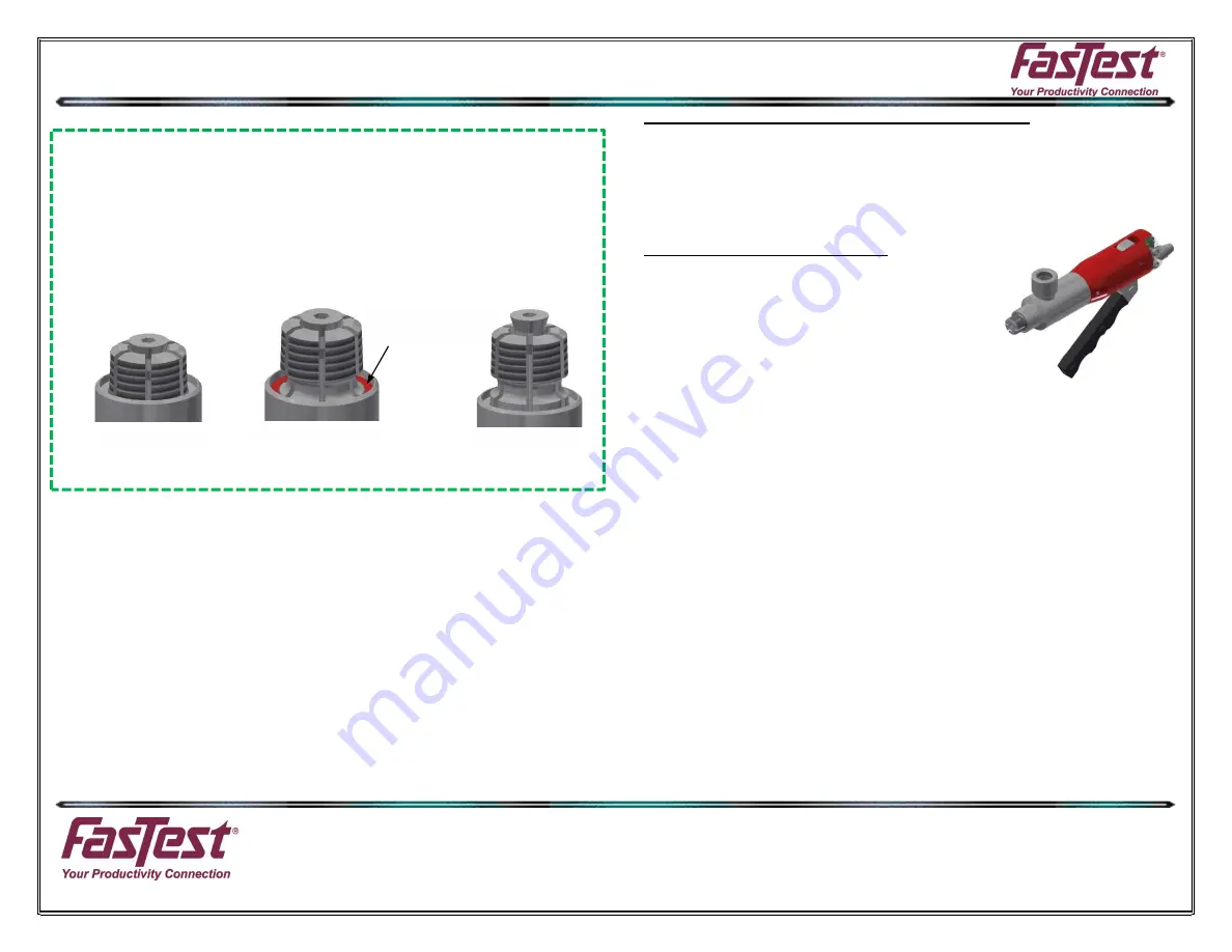
AT REST
TOO FAR
The input is asserted by applying 24V. This can be accomplished by pressing the button
on a FasTest Programming tool, or by using a 24V PLC signal or other 24V logic output.
3.
Flash input 4 times quickly to enter programming mode. Connector will flash 3 times indi-
cating programming mode.
Note: If the first calibration point is not set within about 30
seconds, the connector will return to operational mode.
4.
Do not apply pressure to the handle.
Hold input line high until indicator begins to flash,
about 2 seconds. The first calibration point will be recorded when the input is released.
5.
Squeeze lever handle until the back of the main seal groove on the collet’s lines up with
the flat face of the front body. (See next section for pneumatic connectors). It may be
helpful to remove the main seal for steps 5 and 6
ONLY
.
Note: this location will change depending on thread size and fitting type.
6.
Apply 24V signal to the input line until the indicator begins to flash, about 2 seconds. Re-
lease the input line to record the second calibration point (point B on the graph above).
7.
Release the handle.
8.
Slowly squeeze the handle through its entire movement. Confirm that the proper output is
achieved. Refer to the graph above to see the LED output.
9.
Re-install main seal.
ANALOG CALIBRATION (LEVER AND PNEUMATIC):
A FasMate will not make a good connection if cross-threaded or short-connected. If short-
connected, the piston will sit near or at rest position, and the voltage will be smaller than the
voltage for a good connection. If cross-threaded, the piston will be over-extended, and the voltage
will be larger than for a good connection. To detect a good connection on an analog Sure Seal
TM
FasMate, the voltage must be above the short-connect threshold voltage (V
SC
) and below the
cross-thread detection voltage (V
CT
). This calibration procedure is a guideline for determining
these two voltages, but exact values depend on the user application.
Lever Control (FNL) with Analog:
1.
Rotate red housing to desired location and lock in place
with set screw.
a.
Red housing can be backed out one full turn from
tight. (IDEAL POSITION FOR RED HOUSING IS
TIGHT).
2.
Record the connector’s voltage at rest. The short-connect
voltage (Vsc) will be approximately 0.8V larger than the
voltage at rest but may vary depending on your
application.
3.
Squeeze handle fully.
Note the voltage output at max travel.
4.
Fully insert connector into test piece port and release the lever.
5.
Verify that a good connection has been made. Record the output voltage.
6.
Repeat steps 3-5 several times and record the connector’s voltage.
Use the distribution of
values to determine a cross-thread detection voltage (V
CT
) that is suitable for your
process, e.g. 2 standard deviations above the mean., or the largest voltage observed
for a good connection minus some safety margin.
7.
A good connection is indicated by the output voltage settling in the range between
V
sc
and
V
CT
8.
Once the range is determined, a 24VDC signal may be applied to pins 2 and 5 to provide
red/yellow/green LED indication of connection quality.
* When using Analog, please note that the shielded cable improves noise (single termination); 0-
10VDC is used over operational range of the sensor.
Each time the connector is actuated, the threads can grip in a slightly different position. Therefore,
a range needs to be set during the calibration stage. It is suggested to try and short connect it
several times after the range has been set to ensure the range rejects bad connections. If the
connection falls outside of this range, the system can be setup to alert operators.
CALIBRATION POINT
LINE UP GROOVE
ON COLLETS WITH
THIS INNER FACE


