background image

Inkjet Printer

Operation 

Manual

May 11

th

  2020 Edited V1.1

A470 Series

Summary of Contents for A470 Series

Page 1: ...Inkjet Printer Operation Manual May 11th 2020 Edited V1 1 A470 Series...

Page 2: ...2 3 Control Panel 4 2 4 Hydraulic diagram 5 2 5 Printhead 6 2 6 Ink Core 6 2 7 Main Screen 7 2 8 Menu Analysis 8 2 8 1 Messages 8 2 8 2 Editor 8 2 8 3 User Fields 9 2 8 4 Print 10 2 8 5 Password 10 2...

Page 3: ...he Counter 27 3 5 7 Logo User Field 28 3 5 8 Code User Field 30 3 5 9 External data User Field 31 3 6 Message Parameters 32 3 6 1 Modify message parameters 32 3 7 Print Mode Setting 33 3 7 1 Single Pr...

Page 4: ...the printer maintenance time has expired please notify the service engineer in time 1 2 Safety prevention The installation of the printer should be stable and well grounded The printer must be install...

Page 5: ...nk gloves and safety glasses for those who may touch the consumables 1 4 Handling For machines with ink and solvent in the machine non vertical handling is prohibited If the printer cannot be kept in...

Page 6: ...e WEIGHT Net weight 22kg DIMENSIONS Cabinet 390L 295W 540H Printhead diameter 41mm Printhead length 260mm Nozzle size 60um Umbilical length 2700mm ENVIRONMENT SPECIFICATIONS Operating temperature 5 to...

Page 7: ...Introduction 1 Upper Electronics Compartment Control Panel 2 Lower Ink Compartment 3 Connector Panel 4 Umbilical 2 3 Control Panel Page 4 1 2 3 4 Shortcut keys Diagnosis Screen Input Method Switch In...

Page 8: ...hen the valve is energized I O will open and I N will close 2 When the valve is de energized I N will open and I 0 will close Main ink cycle Consumable adding system Viscosity detection system Automat...

Page 9: ...ction Plate Nozzle Charge Electrode Gutter Pipe Phase Detector Last Chance Filter Nozzle connector Page 6 Exhaust Air Switch Condenser Cover Suction pipe Drain Pipe Exhaust Vent Plug Please remove the...

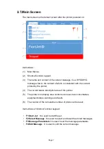
Page 10: ...e current status description area of the printer 5 The printer icon display area contains icons such as consumables equipment status warnings and faults 6 The counter of the cumulative number of print...

Page 11: ...lent to the F3 Message Parameters on the main screen 5 It is used to delete the messages saved in the printer 6 It is used to copy the messages saved in the printer and rename 7 It is used to delete a...

Page 12: ...editor 2 8 3 User Fields 1 Used to edit the saved user fields 2 Used to create new user fields 3 Used to delete saved user fields 4 Used to reset the counter valve in the current message 5 Used to set...

Page 13: ...to set the print modes 4 Used to set the photocell mode 5 Used to set the photocell signal blocking time and mode 6 It is used to set the reverse print mode 2 8 5 Password 1 Enter user password for ad...

Page 14: ...o the lowest authority 2 8 6 System 1 Start the ink jet 2 Quick start the ink jet without a flushing sequence 3 Stop the ink jet Clean the nozzle and related tubes 4 Quick stop the ink jet without a f...

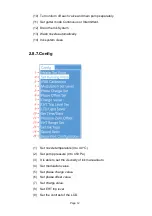
Page 15: ...Wash nozzle automatically 14 Ink system clean 2 8 7 Config 1 Set nozzle temperature 0 to 40 2 Set pump pressure 0 to 450 Pa 3 It is able to set the viscosity of ink manual auto 4 Set modulation value...

Page 16: ...1 Display each of current status of the printer 2 All current operational monitoring data of the printer which are conductive to diagnose malfunctions 3 It can be used to reset counter 4 Display softw...

Page 17: ...abel fill the correct ink and make up to the correct tank push the ink system into the cabin and close the lower cabin door 4 After the manual ink filling operation is completed confirm that the level...

Page 18: ...nutes c After approximately 3 minutes of operation open Valve 7 d After approximately 15 seconds of operation close Valve 7 e After approximately 30 seconds of operation open Valve 7 f Repeat steps e...

Page 19: ...onents are clean and dry 3 Put on the printhead cover press the power button at the right side of the printer and wait for the screen to enter the main operation interface 4 Press F1 to start the prog...

Page 20: ...Observation Side View Front View Page 17 Charge Electrode Nozzle Inkjet The inkjet is at the central position of the gutter pipe Charge Electrode Nozzle The inkjet is about 1 4 of the right side of th...

Page 21: ...hod is as follows 1 Take out the magnifying glass in the standard and place it on the red LED light about 15mm 2 Adjust the distance of the magnifying glass up and down slightly to observe the drops s...

Page 22: ...ked causing permanent damage 3 3 2 Stop Clean Power o during the inkjet running If abnormal stop is caused due to power o inkjet must be restarted at the earliest time after power on It shall be norma...

Page 23: ...to create this message Follow these steps 1 Enter the MESSAGE menu select New Message confirm and enter the screen as shown in the following figure 2 Input file name TEST then press enter key as show...

Page 24: ...lect the Editor menu There are Select Font Insert User Field Save Message Save and Exit Clear Message and Abandon options Message Edit Additional Instructions a key move the cursor in units of one pix...

Page 25: ...to Time then confirm as shown in the figure below 3 Fill the Time Code in the Text field and switch the Print Form to the Form needed if the printing result is digital numbers just keep it as Value 4...

Page 26: ...time user field size is determined by the fonts selected during insertion 3 When the Print Form is Data Matrix or QR Code the Width and Height shall be set according to the standard For details see th...

Page 27: ...3 Figure 6 EAN128 Figure 7 1 Enter the USER FIELD menu select New User Field as shown in the figure below 2 Input a file name switch Attr to Text then confirm as shown in the figure below 3 Fill the c...

Page 28: ...ported size or Coding error appears please modify it to larger height and width for saving 4 Code39 and Code128 are the Barcodes with variable length EAN8 can code the character string with length of...

Page 29: ...SER FIELD menu select New User Field as shown in the figure below 2 Input a file name switch Attr to Counter then confirm as shown in the figure below Instructions of each items refer to 3 5 6 Instruc...

Page 30: ...ar Leading character in front of the counter For example a counter range from 1 to 999 when the print counter is 1 and the leading character is blank space the printing result is 1 When the leading ch...

Page 31: ...n the figure below 2 Input a file name switch Attr to Counter then confirm as shown in the figure below 3 Operation instructions for logo are shown in the following table Page 28 Key combination Funct...

Page 32: ...ter key to confirm the size then enter the Editor menu to save and exit the pattern or use the shortcut Shift F1 to save and exit This pattern can then be recalled and printed within the message Addit...

Page 33: ...ut a file name switch Attr Code then press Enter to confirm When the cursor hovers between Content 1 and Content 6 press F2 to insert in sequence the User Fields to be combined as shown in the figure...

Page 34: ...rsor hov Setting analysis a Number of Char the bit of data transmitted from the computer to the ink jet printer b X0 at the upper right corner of the external data editing interface is the identificat...

Page 35: ...The larger the value is the higher character is Character Gap 0 8 The larger the value is the larger the character spacing is Product Delay 3 1000 0 Set product jet printing delay time The larger the...

Page 36: ...her familiar industries one trigger one printing 1 Select PRINT menu and press Enter to call out the following sub menus 2 Enter Continuous Print sub menu Switch the Continuous Mode to Close then the...

Page 37: ...s continuous processing messages automatic interval printing 1 Select PRINT menu and press Enter to call out the following sub menus 2 Enter Continuous Print sub menu Switch the Continuous Mode to Con...

Page 38: ...press Enter to call out the following sub menus 2 Enter Continuous Print sub menu Switch the Continuous Mode to Times then the printer is in the Times printing mode Repeat times and internal external...

Page 39: ...m should be set as Enable b Shaft Encoder This item should be set as Measure c Photocell 2 FUC This setting is invalid for the Measure Print mode d Pulse per Meter For example if the perimeter of the...

Page 40: ...s of printing per trigger 1 Select PRINT menu and press Enter to call out the following sub menus 2 Enter Continuous Print sub menu Switch the Continuous Mode to Reverse then the printer is in the Rev...

Page 41: ...Opposite Reverse If set it to OPEN the Opposite direction will pint Reverse o and vice versa g Forward Inverse If set it to OPEN the forward direction will pint Inverse o and vice versa h Opposite Inv...

Page 42: ...It is generally 06 10 under normal startup mode 4 Levels Ink Low Ink level in the ink tank now is low Solvent Low Solvent level in the solvent tank now is low 5 Chamber Low High Low high level status...

Page 43: ...it to the best condition incorrect ink stream position Observe the ink stream and adjust it to the best position ink is out of expiration date or polluted Drain the ink and clean the ink system Renew...

Page 44: ...ineer if the display of the icon exceeds 20 min mixer tank full Mixer tank full Please report to maintenance engineer if the display of the icon exceeds 20 min Encoder over speed Synchronizer runs too...

Page 45: ...cter width Wrong breakpoint shape Observe and adjust the breakpoint Refer to 3 2 3 How to Observe Break up point Ink deposited on the gutter pipe Clean the gutter pipe deposited with ink check and adj...

Page 46: ...n shown in the following figure with cleaning agent 4 5 Jet Alignment Horizontal alignment Slightly loosen the screw A and rotate the screw B slightly then the jet stream can be horizontal moved Verti...

Page 47: ...irm Or go to the System menu select Debug and press the enter key to confirm turn on Pump Valve 6 Valve 11 Valve 12 in sequence the ink will instantly start from The OUT port pours out 4 Or go to the...

Page 48: ...4 7 Sensor and Encoder Wiring Diagram 4 7 1 Sensor Diagram 4 7 2 Encoder Diagram Page 45 URZQ ZLUH WR VW SLQ 3RZHU VXSSO ODFN ZLUH WR QG SLQ 6LJQDO ZLUH 1RQH OXH ZLUH WR WK SLQ URXQGLQJ...

Page 49: ...haracteristics of the product without prior notice Manufacturer Name Shanghai Fastjet Electronic Equipment Co Ltd Add No 18 Building Lane 699 Zhangwenmiao Road Fengxian District Shanghai Tel 00 86 21...

Reviews: