background image

NA-1531 / NA-1801 Networking Application Platform Hardware 

Installation Guide 


Introduction


16 

1.6  Rear Panel Outlets 

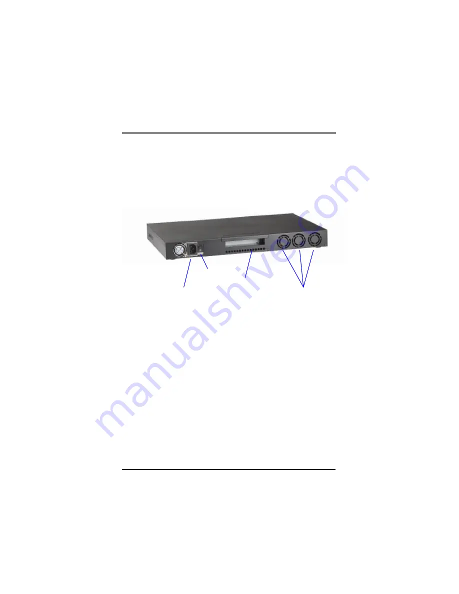
Located at the rear panel of the 

NA-1531 / NA-1801

 server are the I/O 

outlets. You will also find the main power switch and cooling fans. 


Expansion slot – To support one PCI-X 64-bit and  66Mhz slot which is 
for adapter card expansion 


Internal FANs  

Expansion slot 

100-240VAC 

50-60Hz 

Power input  

Power Switch 

Summary of Contents for NA-1531

Page 1: ...FASTORA NA 1531 NA 1801 Hardware Installation Guide For service person only...

Page 2: ...AXIOMTEK makes no commitment to update or to keep current the information contained in this manual AXIOMTEK reserves the right to make improvements to this document and or product at any time and with...

Page 3: ...s However there is no guarantee that interference will not occur in a particular installation If this equipment does cause harmful interference to radio or television reception which can be determined...

Page 4: ...NA 1801 is properly grounded 3 Do not open the system s top cover If opening the coverfor maintenance is a must only a trained technician is allowed to do so Integrated circuits on computer boards ar...

Page 5: ...MA 66 100 hard drive 22 2 2 5 Connectors Jumpers 23 2 2 6 Installation display interface 25 2 2 7 Installation seria interface 26 2 2 8 Installing keyboard and PS 2 mouse connectors 26 2 2 9 Installin...

Page 6: ...vi...

Page 7: ...Table of Contents vii This page does not contain any information...

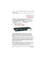
Page 8: ...voice over IP video streaming network bandwidth controller and another networking appliance requirements across this stable and reliable multiple LAN device It is a reliable and affordable 1U height u...

Page 9: ...U loading The NA 1531 NA 1801 can support wonderful networking application platform by excellent cost with performance ratio 1 2 Standard Features l 1U height rack mount stacked up design l High perfo...

Page 10: ...HRP power supplies Standard ATX power input connector l Hard Drive Spacing for 1 x IDE HDD 2 5 l Rear Panel Connector 8 x 10 100 1000 Base T EthernetLAN port For NA 1801 5 x 10 100 1000 Base T and 3 x...

Page 11: ...ort connections are available Two ports of them support LAN by pass feature l Expansion One PCI 64 bit 66Mhz for security encryption card or specialize functions expansion l Compact Flash TM One IDE i...

Page 12: ...NA 1531 NA 1801 Networking Application Platform Hardware Installation Guide Introduction 12...

Page 13: ...Table of Contents 13 1 4 Dimensions Unit mm...

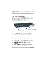
Page 14: ...S 232 Console port for command line interface and diagnostic support by P O S T Power On Self Test Power Lights when the NA 1531 NA 1801 is powered up and performing diagnostic tests to check for prop...

Page 15: ...Table of Contents 15...

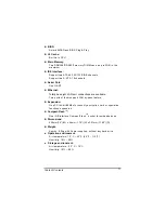
Page 16: ...utlets Located at the rear panel of the NA 1531 NA 1801 server are the I O outlets You will also find the main power switch and cooling fans Expansion slot To support one PCI X 64 bit and 66Mhz slot w...

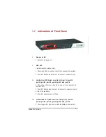
Page 17: ...Link Active LED Single color for LAN port 1 port 2 port 3 port 4 port 5 port 6 port 7 and port 8 1 The yellow LED is on when there is an active connection on the LAN port 2 The LED flashes when there...

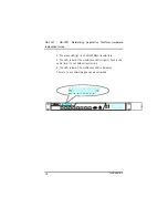
Page 18: ...Introduction 18 2 The green LED light is on 10 100Mbps transfer rate 3 The LED is dark if the Link Active LED is light or flash in the same time It s on 10Mbps transfer rate 4 The LED is dark if the...

Page 19: ...n guide n Mounting screws for disk drive and screws used in this appliance for spare n Quick installation guide n Hardware Installation Guide n NA 1531 NA 1801 cable kits 1 x 40 pin IDE 1 x console ca...

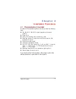
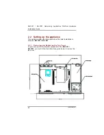
Page 20: ...ting up the appliance This section provides the information about the initial installation to setup the NA 1531 NA 1801 2 2 1 Removing and Replacing the Top Cover To gain access into the internal comp...

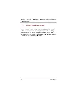
Page 21: ...wo 184 pin DDR socket for a maximum total memory up to 2GB None ECC unbuffer Memory The Intel 875 can support Single and Dual Channel Operation 1 In single channel operation DIMM2 is disabled Only DIM...

Page 22: ...MA 66 100 hard drive To accommodate the fast transfer rate of Ultra DMA 66 100 a cable with 44 pin connectors on both ends is necessary when installing Ultra DMA 66 100 drives The NA 1531 NA 1801 on t...

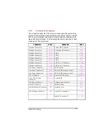
Page 23: ...Ethernet Connector 4 CN14 COM2 CN10 Ethernet Connector 5 CN15 COM3 CN6 Ethernet Connector 6 CN16 COM4 CN7 Ethernet Connector 7 CN 17 USB Port 1 2 Connector R_USB1 Ethernet Connector 8 CN18 USB Port 3...

Page 24: ...Setting 3V Short 1 2 JP2 CF Card Master Slave Setting Master Short 1 2 JP3 4 5 PICMG Slot Usage Setting Normal PCI X Short 1 2 JP6 PICMG Slot VIO setting 3V Short 1 2 4 5 7 8 JP7 CMOS Clear Jumper No...

Page 25: ...rd through the PCI slot 2 2 7 Installing Serial Port Interface The serial interface onboard consists of COM1 port CN19 COM2 CN10 COM3 CN6 and COM4 CN7 supports RS 232 These interfaces could be for LCM...

Page 26: ...signment COM1 COM2 COM3 and COM4 Description COM1 COM2 D SUB 9PIN RS 232 1 1 Data Carrier Delect DCD 2 6 Data Set Ready DSR 3 2 Receive Date RXD 4 7 Request to Send RTS 5 3 Transmit Data TXD 6 8 Clear...

Page 27: ...Connector Optional The Universal Serial Bus USB connector on the main board is for installation of peripherals supporting the USB interface R_USB1 CN2 are the 10 pin USB connector on the main board 2...

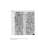
Page 28: ...C with AX89063 connection is should be PIN To PIN assignment The LCD is 16 by 2 it show 16 words in each row And can show totally 32 words with two rows 2 Data transfer format A command 0D hex PC AX89...

Page 29: ...upposedly But it is only can display 1 to 16 words and 41 to 56 words If would like to show the words with two rows of LCM the PC need to send the 80 bytes totally The each character will be fill in i...

Page 30: ...then release the LCM will send 44hex to PC it is ASCII code for D c ESC when it was press then release the LCM will send 4Chex to PC it is ASCII code for L d Enter when it was press then release the...

Page 31: ...Power Supply Specifications 31...

Page 32: ...patible I O system The BIOS provides critical low level support for standard devices such as disk drives serial and parallel ports It also adds virus and password protection as well as special support...

Page 33: ...lso restart by turning the system OFF and back ON again The following message will appear on the screen Press DEL to Enter Setup In general you press the arrow keys to highlight items Enter to select...

Page 34: ...o the CMOS default settings We strongly recommend that you avoid making any changes to the chipset defaults These defaults have been carefully chosen by both Award and your system manufacturer to prov...

Page 35: ...e lower right hand side of the menu is read only It will adjust automatically according to the memory changed The following pages describe each item of this menu Date The date format is day date month...

Page 36: ...Type 1 to Type 45 are predefined Type User is user definable Press PgUp or PgDn to select a numbered hard disk type or type the number and press Enter Note that the specifications of your drive must m...

Page 37: ...field determines whether the system will halt if an error is detected during power up No errors The system boot will halt on any error detected default All errors Whenever the BIOS detects a non fatal...

Page 38: ...cation Platform Hardware Installation Guide Starting the Appliance 38 3 4 Advanced BIOS Features This section allows you to configure and improve your system and allows you to set up some system featu...

Page 39: ...nd display a warning message If this occurs you can either allow the operation to continue or run an anti virus program to locate and remove the problem NOTE Many disk diagnostic programs which attemp...

Page 40: ...oot up sequence The wide range of selection includes Floppy LS120 ZIP100 HDD0 3 SCSI and CDROM Boot Other Device This item allows the user to enable disable the boot device not listed on the First Sec...

Page 41: ...ol For OS This item allows you to select the version of MPS table for NT 4 0 The choice 1 1 1 4 OS Select for DRAM 64MB This segment is specifically created for OS 2 when DRAM is larger than 64MB If y...

Page 42: ...e features in this section are related to the chipset on the CPU board and are completely optimized you are not recommended to change the default settings in this setup table unless you are well orien...

Page 43: ...timing as below CAS Latency Time When synchronous DRAM is installed the number of clock cycles of CAS latency depends on the DRAM timing The Choice 1 5 2 2 5 Active to Precharge Delay This item contro...

Page 44: ...lies only when synchronous DRAM is installed in the system The Choice 2 3 System BIOS Cacheable The ROM BIOS can be mapping to the addresses as F0000h to FFFFFh pass through buffer cache it can speed...

Page 45: ...of thermal diode also be trigged which way to keeping the temperature limitation The choice 4 Min 8 Min 16 Min 32 Min AGP Aperture Size MB AGP Local memory spacing MB The AGP will share addressing of...

Page 46: ...xtra 72 bit to check the data integrity It can correct one bit error We can make the system stability and reliability by this way accordingly If you doesn t have ECC memory deployment you can set the...

Page 47: ...upport for two IDE channels Select Enabled to activate each channel separately The choice Enabled Disabled IDE Primary Secondary Master Slave PIO The four IDE PIO Programmed Input Output fields let yo...

Page 48: ...ve and your system software both support Ultra DMA 33 select Auto to enable BIOS support The Choice Auto Disabled On Chip Primary Secondary Serial ATA The integrated peripheral controller contains an...

Page 49: ...d Onboard Serial Port 1 Port 2 Select an address and corresponding interrupt for the first and second serial ports The choice 3F8 IRQ4 2E8 IRQ3 3E8 IRQ4 2F8 IRQ3 Disabled Auto UART Mode Select This it...

Page 50: ...s option the KB POWER ON Password line appears Press Enter and you ll be prompted to enter and confirm a password of your choice After setting the password succeeding attempts to power ON the system w...

Page 51: ...first and second serial ports The choice 3F8 IRQ4 2E8 IRQ3 3E8 IRQ4 2F8 IRQ3 Disabled Auto UART Mode Select This item allows you to select UART mode The choice IrDA ASKIR Normal RxD TxD Active This i...

Page 52: ...Setup allows you to save energy of your system effectively It will shut down the hard disk and turn OFF video display after a period of inactivity ACPI Function This item allows you to enable disable...

Page 53: ...abled Disabled Suspend Mode When enabled and after the set time of system inactivity all devices except the CPU will be shut off The choice Enabled Disabled HDD Power Down When enabled and after the s...

Page 54: ...us system PCI or Personal Computer Interconnect is a system which allows I O devices to operate at speeds nearing the speed the CPU itself uses when communicating with its own special components This...

Page 55: ...e options available are Enabled and Disabled Resource controlled by The Award Plug and Play BIOS has the capacity to automatically configure all of the boot and Plug and Play compatible devices Howeve...

Page 56: ...NA 1531 NA 1801 Networking Application Platform Hardware Installation Guide Starting the Appliance 56 PCI VGA Palette Snoop Leave this field at Disabled The choice Enabled Disabled...

Page 57: ...d PCI cards must be set to this value Current System Temp Show you the current system temperature Current CPU1 Temperature Show you the current CPU1 temperature Current FAN1 FAN2 FAN3 Speed These opti...

Page 58: ...VBAT 5VSB 12V Show you the voltage of Vcc3 Vcore 2 5V VCC VBAT 5VSB 12V 3 10 Load Optimized Defaults This option allows you to load the default values to your system configuration These default setti...

Page 59: ...Power Supply Specifications 59 3 11 Set Supervisor User Password You can set either supervisor or user password or both of then The differences between are...

Page 60: ...setup menus When you select this function the following message will appear at the center of the screen to assist you in creating a password ENTER PASSWORD T ype the password with eight characters at...

Page 61: ...etup This prevents any unauthorized person from changing your system configuration Additionally when a password is enabled you can also require the BIOS to request a password every time the system reb...

Page 62: ...anges into the CMOS memory Typing N brigs you back to Setup utility Phoenix AwardBIOS CMOS Setup Utility Standard CMOS Features Frequency Voltage Control Advanced BIOS Features Load Fail Safe Defaults...

Page 63: ...tions Typing N will return you to Setup utility Phoenix AwardBIOS CMOS Setup Utility Standard CMOS Features Frequency Voltage Control Advanced BIOS Features Load Fail Safe Defaults Advanced Chipset Fe...

Page 64: ...ghly recommended by the manufacturer Dispose of used batteries according to the manufacturer s instructions l Warning for Hard Disk Drive Selection TUV approved Hard Disk Drive is preferred for TUV co...

Page 65: ...ameplate Make sure the voltage of the power source when connect the equipment to the power outlet The current of load and output power of loads shall be not over the specification This equipment must...

Page 66: ...66 This page does not contain any informati on...

Reviews: