2007-11-19
Page 19 of 35
IT321_Tech_doc_12
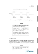
NOTE
With ROM code version the BOOT inputs
can left unconnected (floating) since internal
pull ups are configured to ROM mode as de-
fault.
NOTE
With embedded flash version the BOOT1
and BOOT2 input can be connected to the
same boot control source from host. Normal
operation requires external pull-down resis-
tors connected to the common input, e.g. 0
ohm… 4.7kohm.
4.5 ON_OFF control input
The ON_OFF control input can be used to control the receiver be-
tween Normal or Hibernate modes and also to generate interrupt in
Push-to-Fix operation.
The ON_OFF interrupt is generated by a low-high-low toggle, which
should be longer than 62us and less than 1s (suggestion is abt.
100ms pulse length). Input level is CMOS 1.2V compatible. Do not
generate ON_OFF interrupts less than 1 sec intervals. Especially take
care that any multiple switch bounce pulses are filtered out.
After power up the first ON_OFF interrupt sets the module to Hiber-
nate mode. Next ON_OFF interrupt wakes up the module for Normal
(Navigation) operation. Consequent ON_OFF interrupts switch the
operation mode between Hibernate and Normal modes.
During Hibernate mode internal I/O supply is internally powered off,
thus output levels are at low state and any inputs, excluding ON_OFF
input, like UART RXA should be disconnected or forced to low state.
Summary of Contents for IT321
Page 15: ...2007 11 19 Page 15 of 35 IT321_Tech_doc_12 Figure 2 SiRFFlash utility settings...
Page 25: ...2007 11 19 Page 25 of 35 IT321_Tech_doc_12 Figure 7 Tape and reel specification...
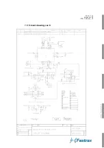
Page 32: ...2007 11 19 Page 32 of 35 IT321_Tech_doc_12 7 3 Circuit drawing rev C...
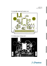
Page 34: ...2007 11 19 Page 34 of 35 IT321_Tech_doc_12 7 6 Artwork layer 2 rev C 7 7 Artwork layer 3 rev C...
Page 35: ...2007 11 19 Page 35 of 35 IT321_Tech_doc_12 7 8 Artwork layer 4 Bottom rev C...

