2010-06-30
Page 33 of 42
IT430_Tech_doc.doc
7
IT430 APPLICATION BOARD
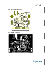
The Fastrax IT430 Application Board provides the IT430 connectivity to the Fastrax Evaluation
Kit or to other evaluation purposes. It provides a single PCB board equipped with the IT430
module, a 1.8V regulator, a 4 channel level translator for 1.8V I/O to 3.3V conversion, an MCX
antenna connector, and a 2x20 pin Card Terminal connector.
Note that Test points are connected only for internal and evaluation purposes and which are not
suggested to be connected in actual applications.
7.1 Card Terminal I/O-connector
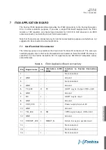
The following signals are available at the 40-pin Card Terminal I/O connector J2. The same pin
numbering applies also to the Fastrax Evaluation Kit pin header J4. Note that UART Port maps to
serial Port 0 at the Fastrax Evaluation Kit. I/O signal levels are CMOS 3.3V compatible unless
stated otherwise.
Table 6
IT430 Application Board connectivity
Pin
Signal name
I/O
Alternative GPIO
name
Interface to Fastrax Evaluation
Kit
1
-
-
-
Not connected
2
GND
-
-
Ground
3
-
-
-
Not connected
4
GND
-
-
Ground
5
TX_3V3
O
TX
UART async. Output, VDD +3.3V
6
GND
-
-
Ground
7
RX
I
-
UART async. input
8
GND
-
-
Ground
9
VDD_3V3
I
-
Power supply input +3.3V
10
GND
-
-
Ground
11
TM_3V3
O
TM
1PPS signal output, VDD +3.3V
12
GND
-
-
Ground
13
XRESET_3V3
I
RESET_N
Active low async. system reset
14
-
-
-
Not connected
15
-
-
-
Not connected
16
-
I
-
Not connected
Summary of Contents for IT430
Page 24: ...2010 06 30 Page 24 of 42 IT430_Tech_doc doc Figure 3 Dimensions ...
Page 38: ...2010 06 30 Page 38 of 42 IT430_Tech_doc doc 7 3 Circuit drawing ...
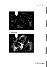
Page 40: ...2010 06 30 Page 40 of 42 IT430_Tech_doc doc 7 6 Artwork layer 2 7 7 Artwork layer 3 ...
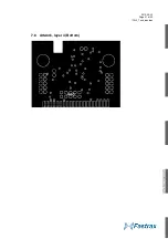
Page 41: ...2010 06 30 Page 41 of 42 IT430_Tech_doc doc 7 8 Artwork layer 4 Bottom ...


