Smart One Installation Guide
D Rehe
6/10/2021
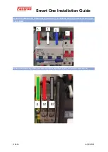
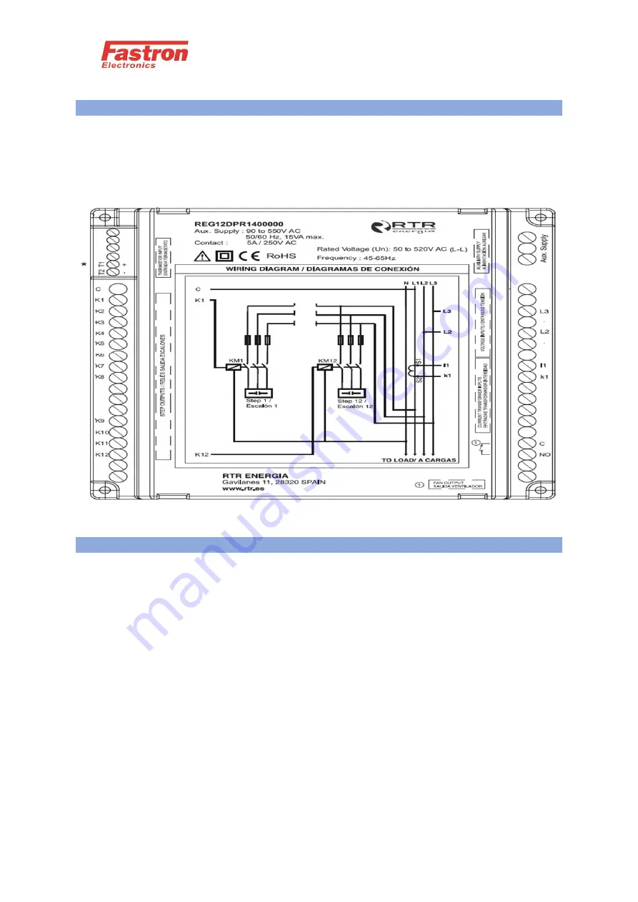
6) Connect CT to S1 and S2 Terminals
-Note the CT Must be connected close to the switchboard in order to measure
the full load current on the switchboard.
-5 Amp Secondary CT’s Must be used
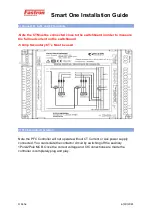
7) PFC Controller Operation
Note the PFC Controller will not operate without CT Current or Aux power supply
connected. You can Isolate the contactor circuit by switching off the auxiliary
1Pole/2Pole MCB. Once the correct voltage and Ct Connections are made the
controller is completely plug and play.

