Edition 3.5
pg 6
Flexitalk manual
4.
Bringing
into
service
the
‘Flexitalk’
All
connections,
except
the
mains
voltage,
happen
via
a
12
‐
pole
clip
line.
It
is
better
to
connect
without
tension.
Under
this
clip
line,
you
find
an
indication
of
the
connections.
It
means:
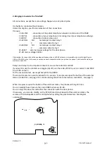
15
‐
16
LINE
:
connection
of
the
public
telephone
network
or
extension
of
the
PABX
17
‐
18
TEL
:
connection
of
your
telephone
or
incoming
line
of
your
telephone
exchange
19
‐
20
DP
:
connection
to
door
phone
unit
21
‐
22
REL1
:
NO
,
normal
open
contact
relay
1
C
,
common
contact
relay
1
23
‐
24
REL2
:
NO
,
normal
open
contact
relay
2
C
,
common
contact
relay
2
25
‐
26
EXT
:
external
supply
voltage
for
the
door
phone
27
‐
28:
mains
voltage
230Vac
Observation:
if
a
connection
with
an
analogue
telephone
line
or
a
PABX
extension
is
impossible,
you
must
bridge
the
pins
LINE
en
DP
with
2
wires.
In
this
case,
you
make
an
audio
connection
when
you
pick
up
the
phone.
To
activate
the
video,
you
must
press
upon
#*#.
Relay
1
and
relay
2
act
as
impulse
contacts
if
you
use
the
code
#1#
and
#2#.
If
you
want
to
use
the
contacts
as
a
toggle
(on/oft),
use
the
codes,
#11#
to
put
on
contact
1
and
#10#
to
put
off
contact
1.
For
the
second
contact,
use
respectively
#21#
and
#20#.
This
second
contact
can
also
be
actived
for
3
seconds
,
if
one
presses
upon
the
button
of
the
external
station
(
code
#511
,
see
page
7)
or
continu
during
the
whole
conversation
(
code
#521
,
see
page
7)
When
one
presses
upon
the
button
of
the
external
station,
the
phones
will
ring
10
times.
You
can
modify
these
times
via
the
code
#
90XX
where
xx=01..99.
You
can
only
introduce
this
code
after
the
connection
with
the
door
phone.
If
necessary,
you
can
also
modify,
on
the
PCB
(Printed
Circuit
Board)
of
the
external
station,
the
volume
of
the
loudspeaker
and
the
microphone
by
setting
the
potentiometers.
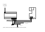
See
diagram
underneath.


