2nd edition, 31-03-2020
7000.05061, 2nd edition, 31-03-2020
7000.05061
Installation
19
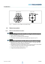
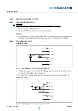
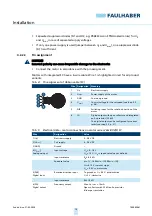
Separated suppressor diodes (D1 and D2, e.g. P6KE33A von STMicroelectronics) for U
P
and U
mot
in case of separated supply voltages.
If only one power supply is used (jumper between U
P
and U
mot
), one suppressor diode
(D1) is sufficient.
4.2.2.3
Pin assignment
NOTICE!
Incorrect polarity can cause irreparable damage to the electronics
Connect the motor in accordance with the pin assignment.
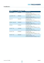
Motors with integrated SC have a 6-wire cable. Wire 1 is highlighted in red for all product
variants.
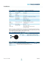
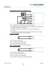
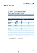
Tab. 4:
Pin assignment of ribbon cable (SC)
Tab. 5:
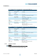
Electrical data – motor connections on motor series 22xx BX4(S) SC
Wire Designation
Meaning
1
U
p
Electronics supply
2
U
mot
Power supply of the motor
3
GND
Common ground
4
U
nsoll
Control voltage for the set speed (see chap. 5.2,
p. 28)
5
DIR
Switching input for the rotation direction of the
motor
6
FG
Digital output with open collector and integrated
pull-up resistor (22 k
Ω
)
The digital output can be configured for various
tasks (see chap. 5.3, p. 31)
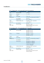
Wire
Designation
Value
1 (U
p
)
Electronics supply
5…28 V DC
2 (U
mot
)
Coil supply
6…28 V DC
3 (GND)
Ground
–
4 (U
nsoll
)
Analogue input
Input voltage
U
in
= 0…10 V
U
in
> 10 V…U
p
➙
speed set value not defined
Input resistance
R
in
≥
8.9 k
Ω
Speed set value
pro 1 V, 1 000 min
-1
(2 000 min
-1
(S))
U
in
< 0.15 V
➙
motor stops
U
in
> 0.3 V
➙
motor runs
5 (DIR)
Digital input
Rotation direction input
To ground or U < 0.5 V: anticlockwise
U > 3 V: clockwise
Input resistance
R
in
≥
10 k
Ω
6 (FG)
Digital output
Frequency output
Max. U
p
, I
max
= 15 mA
Open collector with 22 k
Ω
pull-up resistor
6 lines per revolution

