2nd edition, 31-03-2020
7000.05061, 2nd edition, 31-03-2020
7000.05061
Description of functions
31
5.3
Configuration of the digital output
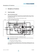
The digital output can be configured for the following tasks:
Fault output
1
When current limitation is activated, the output switches to high level. The delay
between activation of current limitation and setting of the output can be adjusted.
When current limitation is deactivated, the output switches to low level.
Frequency output
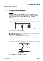
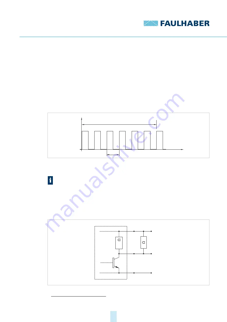
The frequency output can be used to determine the actual motor speed. In this exam-
ple, a signal contains 6 lines per motor revolution.
Fig. 17: Signal structure of frequency output
T
Pulse duration
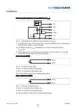
Fig. 18: Connection of an additional pull-up resistor
1
Not available for BRC motors
In order to increase the edge steepness at the digital output, an additional external
pull-up resistor can be connected.
Observe the maximum load capacity of the digital output.
By connecting the internal pull-up resistor (22 k
Ω
) between FG and the supply voltage
U
P
, cable-based electromagnetic RF interference can impair the frequency signal. This
RF interference does not have a negative effect on the speed and rotation direction of
the motor.
6T
U
FG
T
t
U
P
FG
1
6
3
GND
22 k

