2nd edition, 31-03-2020
7000.05061, 2nd edition, 31-03-2020
7000.05061
Installation
18
4.2.2
Electrical connection of motor
4.2.2.1
EMC-compliant installation
NOTICE!
Signal interference may be caused if the connection cables are too long.
Do not exceed a cable length of 3 m.
Observe the EMC protective measures described here.
EMC filter
Each electronics and motor supply cable must be installed directly at the unit with two
windings through a suitable ferrite sleeve (e.g. Würth Elektronik No.: 74270090).
4.2.2.2
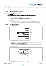
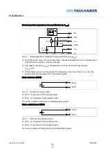
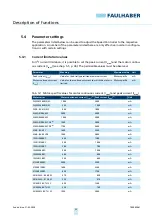
EMC suppressor circuit
Suppressor circuit 1
Fig. 7:
EMC suppressor circuit with ceramic capacitors
If a ceramic capacitor (C1) is used in the PWM
nsoll
operating mode: To avoid faults, use a
signal source with a low internal resistance.
To update the firmware using the Motion Manager software, remove capacitor C2.
Suppressor circuit 2
Fig. 8:
EMC suppressor circuit with suppressor diodes
FG
DIR
U
GND
U
U
nsoll
mot
p
C2
C1
220 nF
220 nF
FG
DIR
U
GND
U
U
nsoll
mot
p
D1
D2
0 – 10 V DC

