2nd edition, 31-03-2020
7000.05061, 2nd edition, 31-03-2020
7000.05061
Installation
20
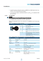
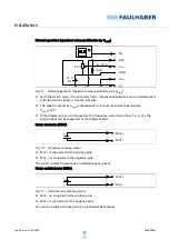
Tab. 6:
Electrical data – motor connections on motor series 32xx BX4 SC
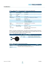
Motors in the version with SCDC have a 2-wire cable. In this operating mode, the servomo-
tor is connected in the same way as a conventional DC motor. The rotation direction of the
motor is determined by the polarity of the connection wires.
Tab. 7:
Pin assignment of ribbon cable (SCDC)
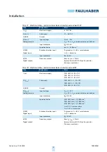
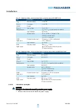
Tab. 8:
Electrical data – motor connection (SCDC)
Wire
Designation
Value
1 (U
p
)
Electronics supply
6.5…30 V DC
2 (U
mot
)
Coil supply
6.5…30 V DC
3 (GND)
Ground
–
4 (U
nsoll
)
Analogue input
Input voltage
U
in
= 0…10 V
U
in
> 10 V…U
p
➙
speed set value not defined
Input resistance
R
in
≥
8.9 k
Ω
Speed set value
pro 1 V, 1 000 min
-1
U
in
< 0.15 V
➙
motor stops
U
in
> 0.3 V
➙
motor runs
5 (DIR)
Digital input
Rotation direction input
To ground or U < 0.5 V: anticlockwise
U > 3 V: clockwise
Input resistance
R
in
≥
10 k
Ω
6 (FG)
Digital output
Frequency output
Max. U
p
, I
max
= 15 mA
Open collector with 22 k
Ω
pull-up resistor
6 lines per revolution
Wire
Designation
Meaning
1 (red)
Mot +
Positive connection of the power supply
2
Mot –
Negative connection of the power supply
Wire (designation)
Value
Voltage
1 (Mot +)
Clockwise rotation with homopolar connection
Anticlockwise rotation with oppositely poled connection
6.5…30 V
2 (Mot –)

