2nd edition, 31-03-2020
7000.05061, 2nd edition, 31-03-2020
7000.05061
Description of functions
24
5
Description of functions
5.1
Operating modes
5.1.1
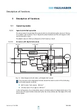
Speed-controlled operation
The actual value for speed used for speed control can be determined by means of the sig-
nals used for commutation. The configurations described below differ with regard to the
used commutation type.
The digital output is factory-configured as the frequency output.
5.1.1.1
BL motors with digital Hall sensors
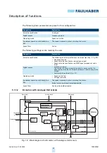
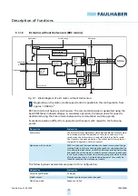
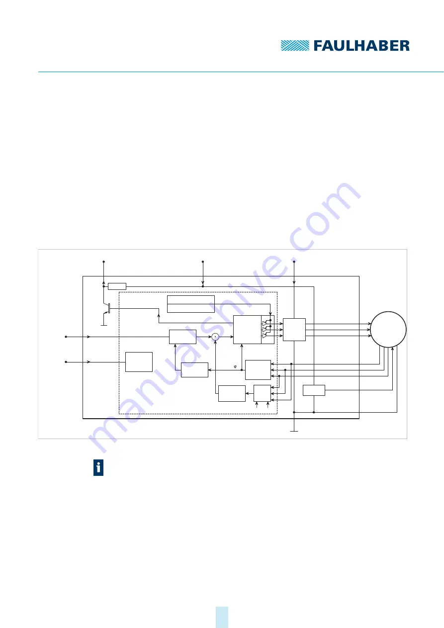
Fig. 12: Block diagram of a BL motor with digital Hall sensors
In this configuration, the commutation signal is determined via the digital Hall sensors. The
actual value for speed is determined using the time interval between the edges of the Hall
sensor signals.
DIR
Rotational direction input
Evaluation
rotational
direction
U
nsoll
n
soll
0 – 10 V DC
Setpoint input
Digital output
FG
22 k
Ω
Electronics supply
U
p
Motor supply
U
mot
GND
MOSFET
Power
output
stage
Protection function:
Overtemperature
Microcontroller
PI velocity
controller
Speed
calculation
Armature
position
calculation
(t)
I²t current
limitation
U
a
3 Phase
PWM
block
commutator
5 V-Control
BL-Motor
Phase A
Phase B
Phase C
Hall sensor A
Hall sensor B
Hall sensor C
VCC
+5 V
Signal GND
I
ist
RM
Motor
model
k
E
The resolution of the digital Hall sensors means that stable control of the following
mechanical speeds is possible:
BXT H series: from approx. 200 min
-1
All other series: from approx. 400 min
-1

