2nd edition, 31-03-2020
7000.05061, 2nd edition, 31-03-2020
7000.05061
Description of functions
25
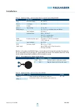
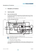
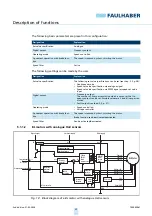
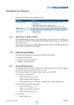
The following basic parameters are preset in this configuration:
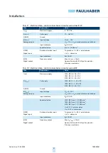
The following settings can be made by the user:
5.1.1.2
BL motors with analogue Hall sensors
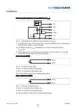
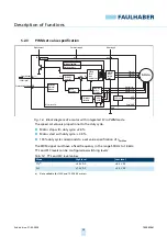
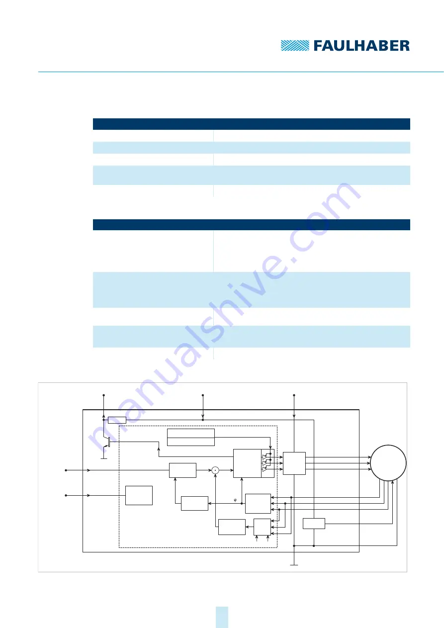
Fig. 13: Block diagram of a BL motor with analogue Hall sensors
Designation
Explanation
Set value specification
Analogue
Digital output
Frequency output
Operating mode
Speed-controlled
2-quadrant operation with brake func-
tion
The speed is reduced by short-circuiting the motor
Speed filter
Active
Designation
Explanation
Set value specification
The following set value specifications can be set (see chap. 5.2, p. 28):
Fixed speed mode
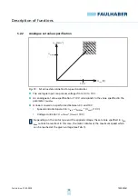
Speed set value specification via analogue signal
Speed set value specification via PWM signal at speed set value
input
Digital output
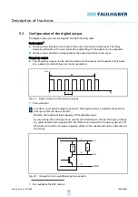
Frequency output:
The number of lines per revolution which is output at the fre-
quency output can be set. Possible values are 2 and 6 lines per rev-
olution.
Fault output (see chap. 5.3, p. 31).
Operating mode
Speed-controlled
Voltage controller
2-quadrant operation with brake func-
tion
The speed is reduced by short-circuiting the motor.
Brake function can be activated/deactivated.
Speed filter
Can be activated/deactivated
DIR
Rotational direction input
Evaluation
rotational
direction
U
nsoll
n
soll
0 – 10 V DC
Setpoint input
Digital output
FG
22 k
Ω
Electronics supply
U
p
Motor supply
U
mot
GND
MOSFET
Power
output
stage
Protection function:
Overtemperature
Microcontroller
PI velocity
controller
Speed
calculation
Armature
position
calculation
(t)
I²t current
limitation
U
a
3 Phase
PWM
block
commutator
5 V-Control
BL-Motor
Phase A
Phase B
Phase C
Hall sensor A
Hall sensor B
Hall sensor C
VCC
+5 V
Signal GND
I
ist
RM
Motor
model
k
E

