2nd edition, 31-03-2020
7000.05061, 2nd edition, 31-03-2020
7000.05061
Description of functions
30
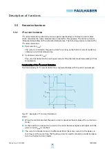
5.2.3
PWM set value specification
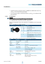
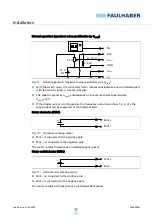
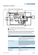
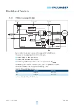
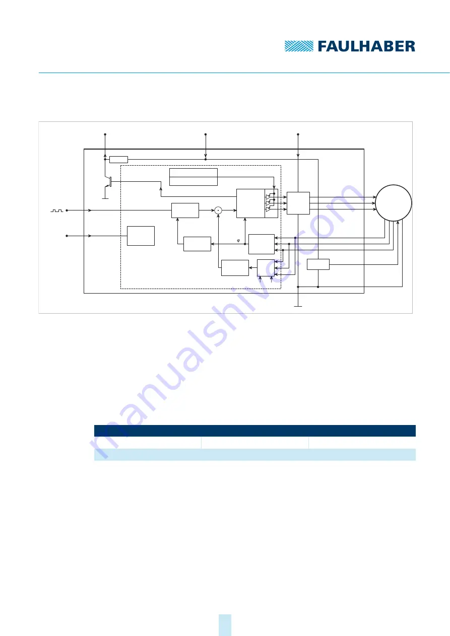
Fig. 16: Block diagram of a motor with integrated SC in PWM mode
The speed set value is proportional to the duty cycle.
Motor stop with duty cycle: <2.0 %
Motor start with duty cycle: >3.0 %
100% duty cycle corresponds to a set value specification of n
setMax
The PWM signal must have a fixed frequency in the range 500 Hz to 18 kHz.
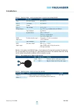
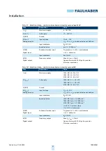
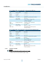
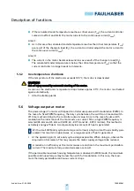
TTL and PLC levels can be configured as switching levels:
Tab. 13: TTL and PLC level values
DIR
Rotational direction input
Evaluation
rotational
direction
U
nsoll
n
soll
Setpoint input
Digital output
FG
22 k
Ω
Electronics supply
U
p
Motor supply
U
mot
GND
MOSFET
Power
output
stage
Protection function:
Overtemperature
Microcontroller
PI velocity
controller
Speed
calculation
Armature
position
calculation
(t)
I²t current
limitation
U
a
3 Phase
PWM
block
commutator
5 V-Control
BL-Motor
Phase A
Phase B
Phase C
Hall sensor A
Hall sensor B
Hall sensor C
VCC
+5 V
Signal GND
I
ist
RM
Motor
model
k
E
PWM signal
Mode
High level
Low level
TTL
a)
a)
Not available for 1525 and 1935 BRC motors
>3.0 V DC
<0.5 V DC
PLC
>7.5 V DC
<2.0 V DC

