2nd edition, 31-03-2020
7000.05061, 2nd edition, 31-03-2020
7000.05061
Product description
9
3
Product description
3.1
General product description
FAULHABER Speed Control Systems are highly dynamic drive systems with controlled speed.
The drive electronics are integrated in the brushless DC-Motors and matched to the respec-
tive motor.
The compact integration of the Speed Controller as well as the flexible connection possibil-
ities enable applications in areas such as laboratory technology and equipment manufactur-
ing, automation technology, pick-and-place machines and machine tools, or pumps.
The integration of the control electronics in space-optimised add-on systems reduces space
requirements and simplifies installation and start-up.
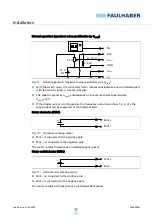
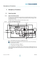
The integrated electronics facilitate speed control by means of a PI controller with external
setpoint input. The direction of rotation can be changed via a separate switching input; the
speed signal can be read out via the frequency output. The motors can optionally be oper-
ated in voltage controller mode or in fixed speed mode.
Depending on the model series, the rotor position is detected by means of digital (option-
ally analogue) Hall sensors or sensorless by means of the induced countervoltage (EMF) of
the motors (model series BRC). The resulting lower speed limits are 1000 min
-1
(sensorless),
200 min
-1
(digital Hall) and 50 min
-1
(analogue Hall).
Depending on the model series, FAULHABER Speed Control Systems (SCS) can be adapted to
the application via the FAULHABER Motion Manager software from version 5.x or 6.x. The
following can be set:
Type and scaling of the set value specification
Operating mode
Controller parameters
The USB programming adapter for Speed Controllers is used for configuration, and a con-
tacting board is used for connecting the cables. The two-wire versions (SCDC) are preconfig-
ured at the factory and the parameters can only be changed by the manufacturer.
The following interfaces and discrete I/Os are available:
Analogue input as set value input for setting the speed via PWM or analogue voltage
value.
Digital input as switching input for defining the direction of rotation of the motor
Digital output, can be programmed either as frequency output or as error output
The following additional functions are available:
Integrated current limitation to protect against thermal overload
Short-time operation with up to double the continuous current
Separate voltage supply for motor and electronics


