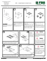
Step III.
Testing the Telephone Network
A) Polarity and Line Voltage
Lightly press the Polarity button. If no
indication is shown by the Red or Green
Polarity LED’s and the Voltage display
LED’s, you may not have the correct
Line selected. Gently slide the Line
Select Switch to the other position and
repeat this step. If you still have no
indication, then neither line is working.
There may be a loose connection,
broken wire, or short in the wiring.
Correct Polarity is shown as Green,
reversed as Red. (Equipment such as
modems, FAX machines, and some
tone-dialing telephones may not work
properly with a reversed polarity line.)
B) Loop Test (Loop Current)
If a Polarity indication was given, lightly
press the button shown for Loop Test.
This will simulate an “off-hook”
telephone. The Red LED will light
brightly if sufficient power is available to
operate a telephone or other device. If
the LED does not shine or is very dim,
either another device is in use or the line
has a partial fault. No Telephone
Network Device can properly operate
with no or insufficient Loop Current.
C) Line / Ring Voltage Display
This display indicates three states of line
condition. With no button pressed, the
BT-10 is in a stand-by mode waiting for
a Ring signal. Use the chart on the back
of the BT-10 as a reference.
When the Polarity button is pressed,
this display will also show the Network’s
Line Voltage. A properly installed and
balanced network will always be
indicated with the Green LED. Yellow
indicates a potentially damaging
Network, Red a poor or damaged
Network needing repair.
D) Testing Telephone line cords.
After verifying proper Network
operation, remove the adapter and
replace with a line cord. Repeat Step
III A & B.
A good line cord should not
change the results of your previous
testing.
Caution Do Not Exceed
Caution Do Not Exceed
Caution Do Not Exceed
Caution Do Not Exceed
150 VRMS to the Test Jack.
150 VRMS to the Test Jack.
150 VRMS to the Test Jack.
150 VRMS to the Test Jack.
The BT-10 should not be permanently
connected to a telephone network. Use
it only to test the network and then
disconnect from the telephone wiring.
Helpful Note for
common wiring
:
Line 1 Tip/Ring as Red and Green.
Line 2 Tip/Ring as Black and Yellow.
©
Faunus, Inc.
Faunus, Inc.
Faunus, Inc.
Faunus, Inc.
2001
.
Polarity
Loop Test
Voltage
Line Select
1
2


