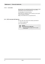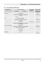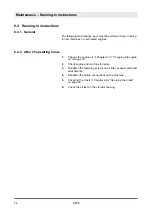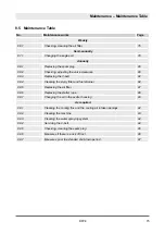
Protective equipment:
n
Working clothes
n
Protective gloves
1.
Park the machine in secured condition
‘Parking the machine in secured condition’ on page 62
2.
Let the engine cool down to 20 °C (68 °F).
3.
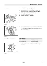
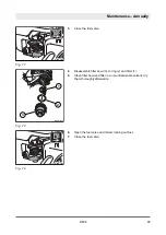
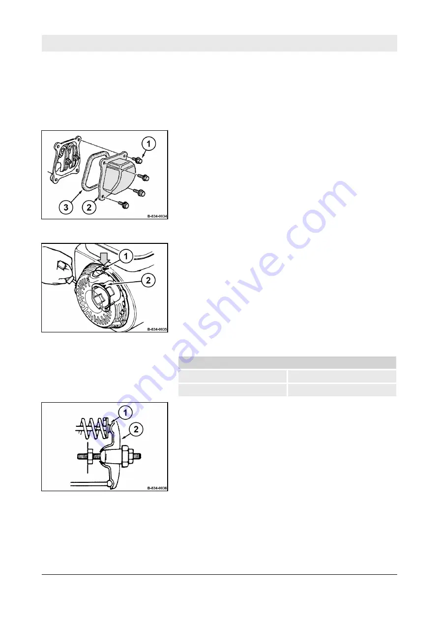
Unscrew the fastening screws (1).
4.
Remove valve cover (2) with seal (3).
5.
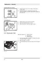
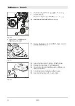
Set the piston to the top dead centre position of the compres-
sion stroke.
For this purpose align the alignment mark (2) on the starter
disc to the top bore (1).
Valve clearance:
Intake valve (IN)
0.15 mm (0.006 in)
Exhaust valve (EX)
0.20 mm (0.008 in)
1.
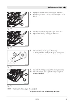
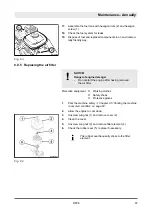
Check the valve clearance with a feeler gauge between
rocker arm (2) and valve shaft (1) on both valves, adjust if
necessary.
Preparations
Fig. 67
Fig. 68
Checking the valve clearance
Fig. 69
Maintenance – Annually
DFP8
81
Summary of Contents for DYNAPAC DFP8
Page 6: ...Table of contents DFP8 6...
Page 7: ...1 Introduction Introduction DFP8 7...
Page 11: ...2 Technical data Technical data DFP8 11...
Page 15: ...3 Concerning your safety Concerning your safety DFP8 15...
Page 39: ...4 Indicators and control elements Indicators and control elements DFP8 39...
Page 45: ...5 Checks prior to start up Checks prior to start up DFP8 45...
Page 52: ...Checks prior to start up Checking the water level topping up DFP8 52...
Page 53: ...6 Operation Operation DFP8 53...
Page 64: ...Operation Parking the machine in secured condition DFP8 64...
Page 65: ...7 Loading transporting the machine Loading transporting the machine DFP8 65...
Page 69: ...8 Maintenance Maintenance DFP8 69...
Page 100: ...Maintenance As required DFP8 100...
Page 101: ...9 Troubleshooting Troubleshooting DFP8 101...
Page 107: ...10 Disposal Disposal DFP8 107...
Page 109: ......
Page 110: ......

