background image

Voltage, polarity and power

Always make sure that any device you connect to this power supply requires the same 
voltage and make note of the minimum amount of power it requires to function properly. If 
an effects pedal requires a minimum of 500 mA, it can not be connected to an output of 100
mA, as this will cause the output to overload.

The outputs on the PBP-06 are all centre-negative, which means that the central conductor 
of the cable's output plug is negative and the part you can see, the barrel, is positive. This is
also indicated per output on the pedal power supply unit itself, and a similar indication is 
probably on the effects pedal as well.

The included adapter cable is a so-called 'polarity changer'. It can be used to change the 
polarity to centre-positive should the pedal you wish to connect require it. 

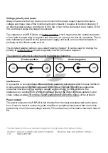
The polarity of a device is shown using the following diagrams:

Centre-positive

Centre-negative

Interference

It is possible to connect many different effects pedals to this device, which makes it difficult 
to solve all possible interference issues with this user manual. Should you experience 
unwanted interference, the cause is usually a ground loop. To find out where the 
interference is coming from, it's recommended to alter the order of effects pedals in your 
chain, replace cables, or remove certain pedals until you find the cause of the problem. 

Power output

The power output on the PBP-06 is fed directly from the input and protected by the same 
fuse. It can be used to connect a guitar amplifier or peripheral equipment that can not be 
powered by one of the low-voltage outputs. This output may not exceed a maximum load of
6A. 

The information in this user manual is subject to change at any time without notice.

Version:
1.0

Date of creation and author's initials: 
08-03-2017 RV

Revision date and author's initials: -

Summary of Contents for PBP-06

Page 1: ...al Power Supply User manual The information in this user manual is subject to change at any time without notice Version 1 0 Date of creation and author s initials 08 03 2017 RV Revision date and author s initials ...

Page 2: ...er cable to mini jack Please inspect the device and the included accessories Should you discover that either the device or one or more of the included parts have been damaged or rendered defective while in transit please contact your dealer directly Please note that the pictures in this user manual serve illustrative purposes only and may differ from the product you receive Contact Fazley musical ...

Page 3: ...ed by a qualified technician Important information regarding safety and health Do not remove any labels or stickers from this device Do not leave any cables lying around The device should not be opened up and any hardware or software that may be present should not be modified To achieve optimal performance inputs on this device should not be fed with a signal higher than necessary The outputs on t...

Page 4: ...aches where there is sand and salt outdoors indoors in spaces where intense heat sources are present or where it reaches temperature levels that would be considered uncomfortable for a person Avoid impact and collisions during use and transport Do not transport the device while it is in use Avoid using excessive force when installing and operating the device The user should become familiar with th...

Page 5: ...evice is disposed of properly This product falls under the WEEE Waste Electrical and Electronic Equipment directive The requirements of this directive apply to all manufacturers and producers of electronic devices in the EU Do not throw this product away with regular rubbish Please contact your local authority for more information about how to recycle and dispose of these products in your region B...

Page 6: ...outputs 200 mA 3 power input via IEC C14 and fuse holder 4 power output via IEC C13 6A max The information in this user manual is subject to change at any time without notice Version 1 0 Date of creation and author s initials 08 03 2017 RV Revision date and author s initials ...

Page 7: ...f this device offer different voltage levels meant for special effects pedals that require a voltage other than 9V DC There is one 500mA output that offers 15V and the other connections may not exceed a load of maximum 300 mA On the right side of this device you will find the regular 9V DC outputs each with a maximum output capacity of 200 mA Each output is also equipped with an LED indicator Simu...

Page 8: ...t The polarity of a device is shown using the following diagrams Centre positive Centre negative Interference It is possible to connect many different effects pedals to this device which makes it difficult to solve all possible interference issues with this user manual Should you experience unwanted interference the cause is usually a ground loop To find out where the interference is coming from i...

Page 9: ... cable is connected properly and plugged into an active mains socket Mains socket not switched on Check that the mains socket is active and switched on if necessary Cable is defective If the cable appears to be defective contact your dealer LEDs do not light up The device is not switched on Connect the device to an active main socket using the included power adapter There is audible interference h...

Page 10: ... DC 300 mA output 4 9V DC 300 mA output 5 10 9V DC 300 mA 230V DC link output max 6 A Technical data type PBP 06 input 115 230V AC 50 60 Hz power consumption 55 W starting current 1 2 A nominal power consumption 480 240 mA fuse F10AL 250V DC outputs 5 5 x 2 1 mm to be used in environmental temperature 0 40 degrees Celsius centre negative polarity short circuit protection overload protection The in...

Reviews: