background image

57 

Remote Condenser Layout 

Summary of Contents for 56 Series

Page 1: ...PO Box 18597 San Antonio Texas 78218 210 637 2800 Tech Support 866 323 2777 After Hours 210 445 2344 56X Frozen Dispenser Training Seminar 24 2285 0001 REV M 02 05 2016 ...

Page 2: ...ptions 21 23 Refrigeration 24 26 Keypad operation 27 29 Menu structure 30 Menu functions 31 51 Thaw Freeze 52 Voltage offset adjustment 53 56 Initial start up and freeze 56 58 E prom replacement 59 Status light definition 60 Electrical diagrams 61 62 Troubleshooting boards 63 66 Transducers 67 CO2 and solution solenoid 68 LCD messages 69 72 Preventive maintenance 73 74 Remote condenser 75 79 Produ...

Page 3: ...of systems in 56X frozen dispenser To equip technicians with basic knowledge to operate 56X frozen dispenser To empower technicians with the understanding of the importance of Preventative Maintenance on 56X frozen dispensers To gain understanding of the Warranty terms and conditions 3 ...

Page 4: ...tage Range 215 245 Current Rating Amp 20 30 20 30 30 Pour Capacity Single Altern oz min 48 64 75 48 64 75 48 64 IPD time Min 12 18 24 Width in 17 20 3 26 Depth in 32 3 Height w o door in 33 9 Height w T door in 41 4 Weight lbs 345 390 460 User Interface Character Display Defrost Logic Customer Dependant Schedule Auto Defrost Blockout times features Control Board Multiple boards Diagnostics 9 Most ...

Page 5: ...age at L1 and L2 Current Rating Amp 20 30 30 Incoming Pressure and Flow Requirements Incoming CO2 PSI 70 72 Regulated CO2 PSI 22 24 Water Pressure PSI 85 92 Syrup Pressure PSI 70 72 Active charge Pressure PSI 28 30 Water Flow Rate at solution module 15oz per 10 second Brix 13 5 15 0 Spacing Requirements Top 12 inches Sides 2 inches Rear 2 inches Tubing Requirements CO2 3 8 Water 3 8 Syrup 3 8 5 ...

Page 6: ...The Four Ingredients The four ingredients to Produce a Frozen Beverage Water Syrup CO2 Electricity 6 ...

Page 7: ...Typical FBD Unit Setup 7 Syrup Pump 1 per barrel CO2 Regulator Syrup BIB Water Source Electrical Source CO2 Source ...

Page 8: ...ery System Model 562 563 564 Solution Module 2 3 4 CO2 Module 2 2 1 Extension 2 2 Extensions Expansion Tank 2 3 4 Active Charge Regulator 1 Syrup Pressure Transducer 2 3 4 CO2 Pressure Transducer 2 Water Pressure Transducer 1 Tank Pressure Transducer 2 3 4 Dispensing Valve 2 3 4 Solenoid 4 6 8 8 ...

Page 9: ...Complete Header Assembly 9 Water Tank Syrup Tank Syrup Regulated CO2 ...

Page 10: ...Counter Clockwise Decreases flow rate 10 Syrup Flow Adjustment Water Flow Adjustment FrontView TopView Water Inlet Solution Outlet Syrup Inlet Tank Pressure Transducer Sample Outlet Sample Valve Syrup Pressure Transducer Water Pressure Transducer Solution Mixing Module ...

Page 11: ...s sold and revenue 2 Prevents drink quality issues based on solution and CO2 ratio CO2 orifice setting is configured to specific water flow rate High water flow rate leads to high solution flow rate and thus low CO2 in the product Low water flow rate leads to low solution flow rate and thus high CO2 in the product 11 ...

Page 12: ...ailure 2 Harness failure 3 Transducer failure The check valve failure symptoms are 1 Water pressure and syrup pressure are within 1 psi difference 2 Can t brix properly 3 Low brix in barrel and can lead to beater low frosty compressor short cycle and compressor run too long 12 ...

Page 13: ...CO2 Inlet TopView FrontView Regulated CO2 Pressure Transducer Solenoid Regulated CO2 Outlet CO2 Pressure Settings Incoming 70 72 psi Regulated 60 2 psi CO2 Pressure Transducer Pressure Regulator CO2 Extension Module ...

Page 14: ...e damage to the water pump Creates different profiles of frozen product Prevents drink quality issues based on solution and CO2 ratio 1 Low regulated CO2 leads to low CO2 flow rate and low CO2 in the product 2 High regulated CO2 leads to high CO2 flow rate and High CO2 in the product 14 ...

Page 15: ...harness from solenoid and measure supply power range from 22VAC to 28VAC 0 volt indicates faulty relay board 22VAC to 28VAC indicates faulty solenoid Faulty shorted solenoid will lead to a burned relay board When required check and replace relay board Troubleshooting Solenoids ...

Page 16: ...Active Charge System 16 Product area before freezing Product area after freezing Diaphragm 70psi 30 psi Active Charge Regulator CO2 ...

Page 17: ...k will be filled with product not allowing for expansion to continue resulting in a P Max Higher than 38 Psig will also cause P Max because of the dead band of the active charge regulator Active Charge Regulator set at 30 psig Turn off machine and dispensing product out of barrel until tank pressure of 0 Psig Measure pressure at active charge regulator with standard tire gauge 17 ...

Page 18: ...ge adjust if needed Expansion Tank Verify if there is a torn bladder by determining whether syrup is on CO2 side of expansion tank Solution CO2 Module Check solenoid seal for tear Check solenoid seating is properly installed PressureTransducer Offset or Harness Check power to pressure transducer is 3 3 DCV Plug into the known pressure and verify pressure readout 18 ...

Page 19: ...P MAX DIAGNOSTIC FLOW CHART 19 ...

Page 20: ...Product Dispensing Valves DDV Valve ADA DDV Valve SDV Valve 20 ...

Page 21: ...Drive Coupler Washer Beater bar w blades Motor Mounting Plate Rear Seal Beater Motor Motor Capacitor Cold Pack Model 562 563 564 Beater bar w blades 2 3 4 Beater Drive Coupling 2 3 4 Motor w Capacitor 2 3 4 Scrapping and Beating System ...

Page 22: ...tem Importance of Scrapping Beating System are To trigger freeze cycle when recognize product in barrel is no long acceptable To scrape ice off of the barrel wall To beat and mix product evenly within the barrel to create consistency 22 ...

Page 23: ...arrel Worn beater blade won t scrap well and thick ice layer Failed capacitor low baseline and high beater Worn motor gear motor failure low baseline and high beater Bad motor winding motor failure low baseline and high beater Rapid compressor cycles Low refrigerant false recognition of beater when freezing Worn beater blade false recognition of beater when freezing Low brix false recognition of b...

Page 24: ...ess Valve Compressor Hot Gas Valve Expansion Valve Cold Pack Evaporator Heat Exchanger Refrigeration Operation Pressures Psig Evaporator Discharge Suction One Barrel 250 275 28 35 Two Barrels 250 275 40 45 Thress Barrels 250 275 45 52 Four Barrels 250 275 48 55 ...

Page 25: ...Temperature Sensor 25 Inlet Temperature Sensor Return Temperature Sensor 562 563 564 Inlet Temperature Sensor 2 3 4 ReturnTemperature Sensor 2 3 4 Total Count 4 6 8 ...

Page 26: ...ck incomplete defrost cycles 2 Sensor fails and reads 40F at evaporator return will starve evaporator 3 Sensor fails and reads 40F at evaporator inlet will lead to refrigerant flood back 4 Sensor fails and reads 97F at evaporator inlet will starve evaporator 5 Both sensors fail will cause machine to shut down and displays hot product shut down Temperature Sensor Sensor Orientation 26 ...

Page 27: ...PC Board Temperature Sensor Connector Location on Aux Board Temperature Connection Configuration P24 P25 P26 JA26 JB26 JC26 562 Barrel 1 Barrel 2 563 Barrel 1 Barrel 2 Barrel 3 564 Barrel 1 Barrel 2 Jumper to JA26 Jumper to P26 Barrel 3 Barrel 4 1 2 3 4 Cold Pack 27 ...

Page 28: ...or Relay Board EEPROM Memory Timer Chip LCD Display Electrical System Model 562 563 564 Eeprom 1 1 1 Relay Board 1 1 1 Main PC 1 1 1 Auxiliary Board 0 0 1 Clock Timer Board 1 1 1 LCD Display 1 1 1 Lower Board 1 1 2 Contactor 1 1 1 Transformer 1 1 1 Compressor Run Cap 1 1 1 Transformer ...

Page 29: ...ser Fan From Contactor T1 T2 Transformer P4 Beater Motor 3 P5 Beater Motor 2 P6 Beater Motor 1 P7 FUSES From Contactor L1 L2 To Contactor Coil 24VAC P8 From Transformer 12 24VAC P9 To Upper Board and LED Merchandiser P10 Beater Motor 3 2 5 amp fuse Voltage Offset Screw Control Signals to from Upper Board DC Power Supply to Upper Board Fluorescent Merchandiser P3 ...

Page 30: ...wer board 30 Beater Motor 4 Transformer Beater Motor 4 SLOW BLOW FUSES From Contactor L1 L2 From Transformer 12 24VAC Auxiliary AUX Board Control Signals to from Auxiliary AUX Board DC Power Supply to Auxiliary AUX Board ...

Page 31: ...31 562 563 Electrical Diagram ...

Page 32: ...32 564 Electrical Diagram ...

Page 33: ...BEFROST Activates and deactivate DEFROST cycle RUN Activates machine to self sustaning running cycle OFF Deactivates machine from self sustaning running cycle CANCEL Exits function menus without making changes BACK Scrolls to left of menu decreses value in settings FORWARD Scrolls to right of menu increases value in settings SELECT Selects changing value finalizes value changes and enters into sub...

Page 34: ...evel of menu until it displays TIME Press select button Value to be changed will blink Press FORWARD or BACK to change setting on blinking value Press CANCEL if you don t want to make changes Press SELECT to finalize value and blinking will stop SS HH MM ...

Page 35: ...s Syrup Press Return Temp Inlet Temp Compressor Fan Defrost Cyc Sold Out Hrs Beater Hrs Run On Hrs Error Hrs Syrup Mins H2O Pressure CO2 Pressure Regulated CO2 Line volt Side Set Shared Side Common Side Common Side Common Side Common Set Totals Are You Sure Are You Sure Are You Sure Bevtrak Only on units with auto defrost Blackout Defrost Auto Defrost Sides Defrost Fan Daylight Savings Version Cop...

Page 36: ...S Sets Machine to Turn Off On Throughout the Week FAULT CODE HISTORY Stores 10 Faults Display Error Codes Start End Time SERVICE MENU Blank Key on Side 1 to Enter SOFTWARE VERSION Displays Software Version and Revision BEEPER ENB Enables or Disables Audible Alarm ALT LANG Alternates LCD Language ES Enables or Disables Energy Savings Functions Daylight Savings Version Copyright Fault Code History T...

Page 37: ...g Range 0 6 Defaulted at 3 Thaw Freeze Setting Range 0 20 Defaulted at 10 FUB Mode Allows Customer to Formulate Non Carbonated Product Defaulted at OFF COMMON SER Enter Serial Installation Defaulted at 99999999 Volt Offset Compensates the Differences Between LCD and Measured Line voltage Blink Out of Sold Out Light Stays on Solid Rather than Blink When Enabled 37 ...

Page 38: ... PRESS Indication of Pressure in Barrel SYRUP PRESS Indication of Syrup Pressure RETURN TEMP Indication of Refrigerant Temperature Flowing Out of Barrel INLET TEMP Indication of Refrigerant Temperature Flowing Into Barrel COMMON H2O PRESS Indication of Water Pressure CO2 PRESS Indication of CO2 Pressure REGULATED CO2 Indication of Secondary Regulated CO2 pressure LINE VOLTAGE Indication of Line Vo...

Page 39: ...id SOLUTION SOL Activate and Deactivate Solenoid BEATER MOTOR Activate and Deactivate Beater Motor DEFROST SOL Activate and Deactivate Solenoid REFRIG SOL Activate and Deactivate Solenoid PRODUCT OUT Activate and Deactivate Product Out Lights ANNUN ITEMS Activate and Deactivate Annunicator Lights COMMON COMPRESSOR Activate and Deactivate Compressor FAN Activate and Deactivate Fan 39 ...

Page 40: ...al Motor was In Operation Hours RUN ON HRS Total Compressor On Hours ERROR HRS Total Error Hours SYRUP MINS Total Syrup Minutes COMMON COMP HRS Total Compressor On Hours COMP CYL Total Compressor Cycles POWER ON HRS Total Machine On Time SLEEP HRS Total Sleep Hours SET TOTALS SIDE Reset Operation Time within Side ARE YOU SURE Yes to Reset No to Cancel Reset SET SHARED Reset Common Operation Time A...

Page 41: ...rface Level Menu Manual On Off Machine Settings Readouts Machine Totals Load All Defaults Are You Sure Bevtrak LOAD ALL DEFAULTS Restore Settings to Factory Settings Are You Sure Yes to Reset No to Cancel Reset 41 ...

Page 42: ...tes the effects of change in Refill and Full pressure Higher Barrel pressure represents higher expansion Lower Barrel pressure represents lower expansion EXPANSION SETTINGS VALUE REFILL FULL Recommended Active Charge Pressure 0 22 5 24 5 26 1 23 25 26 5 2 23 5 25 5 27 3 24 26 27 5 4 24 5 26 5 28 5 25 27 28 5 6 26 27 5 29 ...

Page 43: ...890 8 795 895 10 800 900 12 805 905 14 810 910 16 815 915 18 820 920 20 825 925 Thaw Freeze setting is used to increase or decrease Freeze and Thaw Table below demonstrates the effects of change in Freeze and Thaw beater High beater represents liquidly frozen product Low beater represents firmer frozen product 43 ...

Page 44: ...t Offset Blink Out of Machine Settings Readouts H2O Pressure CO2 Pressure Regulated CO2 Line volt Common Side Side Common L1 Connection L2 Connection Measure L1 and L2 voltage at contactor when machine is off Turn the Potentiometer on the primary lower power board until the LCD Line Volt matches measured voltage Turning Clockwise to decrease Turning Counter Clockwise to increase Method 1 Voltage O...

Page 45: ...d verify tolerances are within 5 of 15 15 and 5 DC voltage On a old board D16 blinks when 5V is present New board doesn t have indication lights If 5V is not present Check harness for continuity and verify LPB DC test points Replace harness if harness is bad Replace upper board if harness and LPB are good Troubleshooting UPB ...

Page 46: ...Power Board TP3 15VDC analog voltage for temp pressure sensor readouts TP5 15VDC analog voltage for temp pressure sensor readings TP6 5VDC for micro processor and EPROM TP7 Ground D TP8 Ground A TP9 5 12 for micro processor TP10 5 12 for pressure sensors TP2 TP3 TP5 TP6 TP10 TP9 TP7 TP8 TP1 Test Points UPB 46 ...

Page 47: ...ct power to machine 3 Remove old E PROM with chip puller 4 Install new E PROM with notch up 5 Reconnect power to machine Wait 1 minute for software to load 6 Scroll to Load All Defaults to reset 7 Re enter recorded values from step 1 back to the machine settings 8 Press Off Defrost then Run for each barrel 47 Notch Up ...

Page 48: ... Ground TP 4 GND to check voltage at test points TP 1 15VDC TP 2 5VDC and TP 3 15VDC If voltage not present test voltage at TP8 for 24VAC and TP18 for 12VAC which comes from Transformer If voltage is present replace LPB If voltage is not present replace Transformer 48 Troubleshooting LPB Ground L2 L1 Lower power board TP18 TP 8 12VAC 24VAC TP 1 5VDC TP 2 15VDC TP 3 15VDC TP 4 Ground ...

Page 49: ...t connections on LPB at P12 Measure across L 1 pin on P 12 connector to GND voltage will range from 85vac to 125 vac If voltage is present manually turn on Condenser Fan using the Manual on off controls in the menus Test for voltage across L1 pin and L2 pin from P 12 connector Voltage will range from 208 to 230 vac depending on Incoming voltage If voltage is not present replace LPB If voltage is p...

Page 50: ...ir 5 Press the FILL Beater button to fill barrel Fill barrel to just below the Relief Vent Valve NOTE In the filling process motor will need to be stopped to check filling level and relief vent valve will be pulled to allow filling 6 Press the OFF the Defrost then the Run button 7 Verify and or update the Time Date DL Savings where applicable Wake Sleep Time and Defrost Times 8 After freeze down p...

Page 51: ...Status Lights 51 Annunciator Pad Sold Out Light ...

Page 52: ...perature 9 TnkPsi ERRORz During fillingtank pressure transducer stays a 0 psi for 30 sec 10 SFilEr ERRORs During fillingtank pressure transducer stays below Refillvalue for 1 min 11 BTR LO ERRORl Beater drops below 200 or 300 and triggers a defrost cycle 12 BTR HI ERRORh Beater is above 1200 13 CO2out CO2OUT CO2 pressure is below 35 psi 14 H2Oout H2oOUT Water pressure is below 35 psi 15 SyrOut SYR...

Page 53: ...nFrz Commanding reeze down cycle in the machine READY mode 32 RunFWt Running freeze down cycle in the machine READY mode 33 RunTha Machine is in Thaw state but in READY mode 34 RUNThW Transitionfrom RunTha to RunFrz 35 PresMx Tank pressure is above 55 psi 36 RunPrO Product out in the freeze down process 37 Fillng Machine in filling mode has not satisfiedthe FULL pressure value 38 Fill H Tank press...

Page 54: ...ual inspections for leaks 4 Replace rear seals per PM recommendation and repair DDV valve as needed 5 Sanitize unit following recommended procedures 6 Clean air filter 7 Follow Initial Start Up and Freeze procedure to start machine 54 Recommended replacement time 6 months Approximate PM time for 564 1 5 hours PM Parts Needed Rear Seals Dow 111 lubricant ...

Page 55: ...Remote Condenser 55 ...

Page 56: ...alling a dual remote condenser follow the same procedure for both sides When construction site is ready return and complete installation Hoist remote condenser s onto roof and place onto sleepers Coordinate with other refrigeration contractor and share cost of the crane when HVAC and walk in units are installed if possible NOTE Modify installation as needed to meet all local and state building cod...

Page 57: ...57 Remote Condenser Layout ...

Page 58: ...Remote Trap Layout 58 ...

Page 59: ...Remote Refrigerant Charge Matrix Heatcraft remote condenser FBD remote condenser 59 ...

Page 60: ...Product Warranty 60 ...

Page 61: ...destruction or damage caused by alterations using parts other than FBD authorized replacement parts risks of transportation damage by fire flood or acts of God Moreover the warranty does not apply to any damage caused failure to install machines parts or equipment in accordance with the applicable FBD manual s interruption of electrical power to the FBD machines or failure to perform cleaning and ...

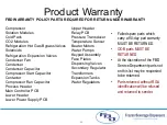
Page 62: ...Lower Header Lower Power Supply PCB Upper Header Relay PCB Pressure Transducer Temperature Sensor Beater Motors Water Pumps Keypad Assembly Face Plates Dispensing Valves Secondary Regulator Transformers Expansion Tanks Water Regulators Failed spare parts which carry a 90 day part warranty MUST BE RETURNED OOB parts MUST BE RETURNED At the discretion of the FBD Service Department parts not on this ...

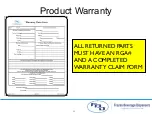
Page 63: ...63 ALL RETURNED PARTS MUST HAVE AN RGA AND A COMPLETED WARRANTY CLAIM FORM Product Warranty ...

Page 64: ...Thank you 64 ...

Reviews: