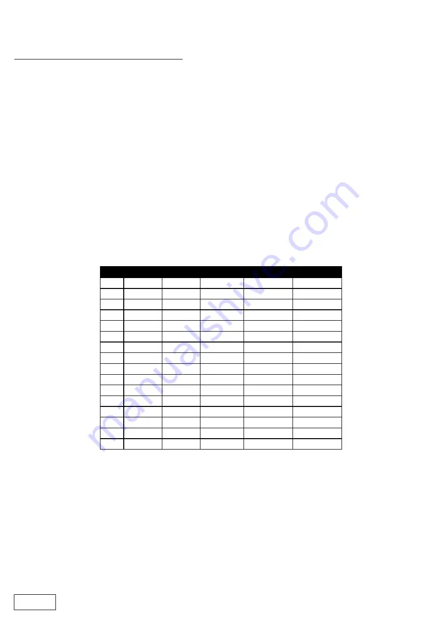
dB
Ratio
Vrms
Pwr 8
Ω
Pwr 4
Ω
Pwr 2
Ω
45
177.83
137.74
2371.71
4743.42
9486.83
44
158.49
122.77
1883.91
3767.83
7535.66
43
141.25
109.41
1496.45
2992.89
5985.79
42
125.89
97.52
1188.67
2377.34
4754.68
41
112.20
86.91
944.19
1888.39
3776.78
40
100.00
77.46
750.00
1500.00
3000.00
39
89.13
69.04
595.75
1191.49
2382.98
38
79.43
61.53
473.22
946.44
1892.87
37
70.79
54.84
375.89
751.78
1503.56
36
63.10
48.87
298.58
597.16
1194.32
35
56.23
43.56
237.17
474.34
948.68
34
50.12
38.82
188.39
376.78
753.57
33
44.67
34.60
149.64
299.29
598.58
32
39.81
30.84
118.87
237.73
475.47
31
35.48
27.48
94.42
188.84
377.68
30
31.62
24.49
75.00
150.00
300.00
Setting Accurate Limiter Thresholds
The limiters built into the SP27 Series are intended to be used for loudspeaker driver protection, as opposed to
amplifier protection. All modern professional power amplifiers designed for live sound use have their own
limiters, which are tailored to protecting the amplifier from clipping.
The following section describes how to set up the units' limiters to provide exceptional protection against driver
overheating, and cone over-excursion.
Most speaker systems are given a power rating in Watts RMS. This is the maximum continuous power that
the system will handle and often appears very conservative. In reality, as music program is far from
continuous in nature, the peak power of the system is much higher – up to ten times the continuous figure.
Any limiter, which is to protect the driver from damage, must be able to fulfil the following tasks.
·
Have an attack time which is calculated to allow transients through but keep the RMS level below the
speaker manufacturers specification;
·
Have a release time which is sufficiently long to avoid the limiter itself modulating the program;
·
Be intelligent enough to adjust the envelope of the limiter according to the frequency content of the
program material.
The program limiters are capable of performing all these tasks. The only parameter that the user must set
manually is the threshold, and it is crucial that this is done correctly. Consider the table below.
Using this table it is a straightforward procedure to work out the required setting of the limiter thresholds for the
system.
“
First, check the RMS power rating of the speaker system, and its impedance.
“
Look up this value in the table above, using the closest value below the rated power of the speaker
system. Note the corresponding 'dB' value.
”
Check the gain of your amplifier, which needs to be in 'dB'.
”
Subtract FROM this gain figure that obtained from the table to find the required absolute setting for the
limiter thresholds.
Note that, for safety, always set the limiter threshold 1 or 2 dB below the maximum allowable worked out using
the above method.
ALWAYS REFER TO YOUR SPEAKER MANUFACTURER FOR LIMITER SETTINGS.
ALERT
31
Summary of Contents for QUBE SP27
Page 1: ...QUBE SP27 Audio Management System www qubeaudio com FBT ELETTRONICA S p A www fbt it ...
Page 2: ......
Page 13: ...2 x 3 way crossover 1 x 6 way crossover 2 x 2 way mono 11 ...
Page 20: ...Menu System Overview 18 ...
Page 41: ...Appendix I SP27 Default Crossover Configurations 2 x 3 Way 39 ...
Page 42: ...2 x 2 Way Mono Sum 40 ...
Page 43: ...1 x 6 Way 41 ...


