FS10 Series
INSTALLATION
Fluid Components International LLC
9
1A 120 VAC/24 VDC
JP5 = 2-3
RELAY CONTACT RATED CURRENT:
OUTPUT PULSE SOURCE
OUTPUT PULSE SINK
OPEN COLLECTOR
OUTPUT RELAY (Default Setting)
2N7002
4.3K
S
OUTPUT ALARM
SETPOINT
OUTPUT ALARM
SETPOINT
10K
10K
G
D
Q3
+24VDC
V
CC
JP8 = IN
JP8 = IN
JP5 = OUT
NOTE:
2N7002
S
G
D
Q3
CUSTOMER POWER SOURCE
AND LOAD NOT TO EXCEED
50 VDC and 40 mA.
2N7002
S
+24V
G
D
Q3
-
+
COIL
K1
NO
NC
C
JP8 = OUT
JP5 = 1-2
FREQUENCY OUTPUT CORRESPONDING
TO FLOW WITH PULSE WIDTH AT 50%
DUTY CYCLE FOR RATES 1 TO 2000 Hz.
5.5 mA LOAD PULSED.
RECOMMENDED LOAD RESISTOR = 10 K
Ω
ALARM FUNCTION (SETPOINT).
FREQUENCY OUTPUT CORRESPONDING
TO FLOW WITH PULSE WIDTH AT 50%
DUTY CYCLE FOR RATES 1 - 2000 Hz.
RECOMMENDED LOAD RESISTOR = 10 K
Ω
ALARM FUNCTION (SETPOINT).
SW_OUTPUT
OR OUTPUT
FREQUENCY
SW_OUTPUT
H OR H
L
L
OR OUTPUT
FREQUENCY
H OR H
L
L
OUTPUT ALARM SETPOINT
SW_OUTPUT
C01265-1-1
DIODE CONNECTED IN
REVERSE BIAS
D
1
POLARITY OF CIRCUIT
VOLTAGE
C01038-1-1
RELAY COIL
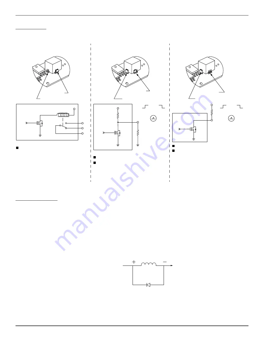
Switching Inductive Loads
If the FS10A/FS10i relay contacts are to be used to energize or de-energize an external relay, diode suppression must be used across the external
relay coil. Use the guidelines in the following example to select the proper diode.
A Tyco Electronics relay K10P-11D15-24 is used as a slave relay. The DC coil voltage is specified at 24 VDC and the specification indicates a coil
resistance of 650
Ω
. The DC coil current is calculated by dividing the rated coil power by the rated voltage VDC or dividing the rated voltage VDC by
the coil resistance. In this case the current through the coil will be around 37 mA (24 ÷ 650). Refer to the K10P-11D15-24 data sheet.
It is recommended the diode reverse voltage (Vr) rating be twice or greater the voltage across the relay and the diode forward current (IF) rating be
greater than the relay current. Diodes 1N914 or 1N4148 meet these limits for this case.
FS10 Output Modes
A schematic view of the FS10 output modes and corresponding jumper settings are shown below.
Figure 8 – Output Modes and Jumper Settings
Figure 9 – Relay Coil Suppression Diode


