FS10 Series
INSTALLATION
Fluid Components International LLC
17
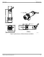
U-Length = 2.00
[51]
U-Length = 2.00
[51]
U-Length = 2.00
[51]
U-Length = 4.00
[102]
U-Length = 6.00 max.
[152 max.]
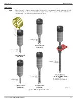
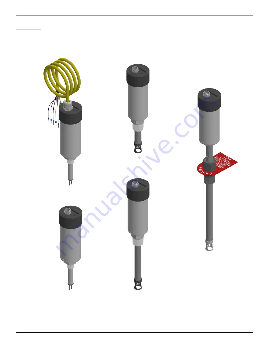
CONFIGURATION:
FS10i-B10X
CONFIGURATION:
FS10i-C20X
CONFIGURATION:
FS10i-E20X (Teflon Ferrule)
or
FS10i-F20X (Metal Ferrule)
CONFIGURATION:
FS10i-B20X
CONFIGURATION:
FS10i-D20X
C01360-1-2
FS10i Drawings
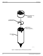
Note:
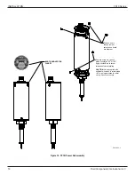
An FS10i housing is secured with removable screws. The original FS10A housing was secured with fixed pins that were not
removable in the field. Later versions of the FS10A are supplied with removable housing screws. The disassembly instruc-
tions below apply to any FS10 unit with removable housing screws.
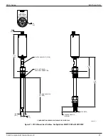
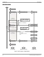
Figure 17 – FS10i Configuration Overview


