OPERATION
FS10 Series
26
Fluid Components International LLC
Mode B: Capture Zero and Full Scale + Set Default Switch Point
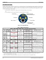
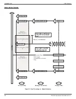
1. After pressing the (+) or (–) button for 10+ seconds, the 3 outside LEDs sequentially flash in opposite directions. Release the button at this
point to enter Mode B. The FS10 is now cued to remember the lowest and highest flow signal it sees while in this mode.
2. Adjust high flow to represent span setting and low flow (or no flow) to represent the zero as described below:
For Gas
: It is recommended that the flow be at the desired full-scale value
before
entering this mode. After entering the mode, slowly
reduce the flow until the zero flow is reached. Setting the low flow to around 10% yields more linear results over the entire range as this
zero offset removes a steep portion of the curve.
For Liquid
: It is recommended that the line be full with no flow
before
entering this mode. After entering the mode, slowly throttle the
valve to full-scale.
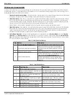
3. After giving the instrument zero and full-scale flow, momentarily press the (+) button or (–) button to choose an alarm fail-safe and exit
the Mode B range capture mode:
Note:
Unit remains in learning mode indefinitely until either the (+) or (–) button is momentarily pressed.
• Fail-safe Low (–/minus): Default switch point is set to 30% of span.
• Fail-safe High (+/plus): Default switch point is set to 70% of span.
4. After exiting the range capture mode, the LED representing the default switch point blinks rapidly for 5 seconds.
• It is during this
5-second window
that adjustments to the switch point setting can be made if needed.
Press the the (+) or (–) buttons increment or decrement the switch point setting in 5% intervals of the newly established span (observe
that the blinking LED moves in response to button presses). After 5 seconds of button inactivity, the unit flashes the end LEDs 5 times
in alternate fashion to indicate that the setting was accepted. The unit then returns to regular operation as the switch point LED blinks
normally (and in its new switch point location if moved).
Note
:
Switch point LED blink rate, normal operation: Slow = Not In Alarm; Fast = In Alarm (trip point exceeded).
A minimum span setting of 2% in gas (–) button or 0.05% in liquid (+) button is required to save new parameters. If minimum span is not
reached, the first two, middle two and last two LEDs flash for 3 seconds to indicate an error. The unit then resumes the last operation with no
change in parameters.
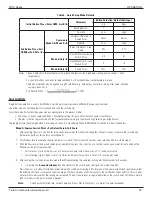
Definition of fail-safe parameters upon exiting:
(–) Minus Button Exit = Low Flow Alarm = Fail-Safe Low
Relay polarity = 1 (Relay energized above the switch point)
Hysteresis position = 1 (Reset above the switch point)
NAMUR fault = 1 (Fault low; Analog Output drives to <3.6mA), relay drives to fail-safe position
(+) Plus Button Exit = High Flow Alarm = Fail-Safe High
Relay polarity = 0 (Relay energized below the switch point)
Hysteresis position = 0 (Reset below the switch point)
NAMUR fault = 2 (Fault high; Analog Output drives to >21mA), relay drives to fail-safe position
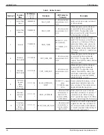
These default parameters can be changed through the PC interface program or factory setup by completing the Application Data Sheet (ADS)
at time of order.


