FS10 Series
OPERATION
Fluid Components International LLC
27
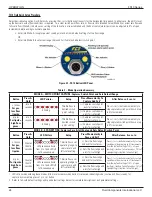
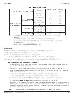
Quick Setup Mode Recommendations
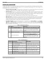
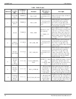
Mode A: Switch Point Capture With Default Zero & Full Scale
If only a zero flow can be simulated, set flow to zero flow (if liquid, make sure line is full). Then enter into Mode A to capture switch point at
no flow. Immediately after exiting, momentarily press the (+) button to increment the switch point in 5% steps to set the actual trip above the
actual no flow reading.
If throttling the flow is not possible and the switch can only be set under normal flow conditions, set the switch point at this normal flow, then just
after exiting, momentarily press the (–) button a number of times decrementing to an alarm point well below the normal flow. Each press of the
(–) button lowers the switch point approximately 5%. After 5 seconds the FS10 returns to normal operating mode with new settings in place.
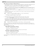
Mode B: Range Capture With Default Switch Point
Gas Applications
– The high flow limit or span setting is normally the most difficult to stabilize in a gas application. Therefore, simulat-
ing the desired high flow rate at normal process conditions and allowing it to stabilize before entering into the QSM is recommended. Using
in-line valves or other means of throttling establish the desired full scale flow rate and allow the system to stabilize. Now enter into QSM 2
(capture/exit)—the FS10 immediately captures this high flow signal. Then slowly throttle the flow down until the zero flow setting is reached
(i.e. valve closed, no flow). Allow to stabilize, then momentarily press appropriate fail-safe button to save parameters and return to normal
operating mode with the new scaled operating range established.
Note:
If using the 4-20 mA output, create a zero offset to significantly improve the linearization of that output; i.e., instead of
scaling between 0 and 10 SCFH (0 to 5000 cc/min), establish the zero and span from 1 to 10 SCFH (500 to 5000 cc/min). This
method yields a more accurate representation of the switch point, set at 30% (or 70%) of the span by default.
Liquid Applications
– To optimize the performance of the FS10 in liquids, it is critical to establish a stable zero setting under a packed line
condition. It is recommended that the FS10 be operating and allowed to come to equilibrium with a downstream valve closed and the line
completely filled with the process fluid and no flow. At this point, enter into QSM 2 (capture/exit)—the FS10 immediately captures this low
flow signal. Then slowly open the downstream valve to allow flow up to the maximum span desired. Momentarily press the appropriate fail-
safe button to save parameters and return to normal operating mode with the newly scaled operating range established.
In some cases the high liquid flow signal will saturate before reaching the high flow that is simulated. The FS10 will save the highest value it
is capable of sensing in that application and use it as the high end limit.
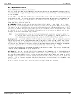
Switch Point
– By factory default, the switch point is set to 30% (fail-safe low) or 70% (fail-safe high) of the established span when exiting
the Quick Setup Mode. This may be adjusted in 5% increments in the field within 5 seconds of exiting per above instructions. Alternatively,
the QSM factory switch point default of 30% (or 70%) of span can be changed using the PC interface program before entering into the QSM.
Selecting the factory setup option at time of order by completing the Application Data Sheet (ADS) also sets up a custom default value at the
factory. Note that this value is always a percentage of the established span and alters any previous switch point that may have been attained
on a previous setup.
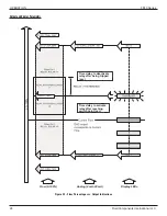
The 4-20 mA output and relay trip continues to operate at the previously set range while in the Quick Setup Mode.

