FS10 Series
OPERATION
Fluid Components International LLC
31
Normal Set-Up and Operation Using the Button Interface
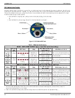
Refer to “Table 7 – Button Controls” on page 30 for details on the functions listed in the descriptions below.
Flow Switch Scaling
Units supplied without factory switch point setting should be scaled in situ before setting the switch point. Default Universal Setting A from
Bank 1 is recommended for most low flow sampling gas or liquid service. Universal Setting B from Bank 3 is recommended for gas or liquid
service applications where higher flow rate detection is required.
Scaling is performed in the following order:
Minimum Flow Setting (Function 6)
– Select Function 6 to capture the minimum flow rate. In liquids, optimum performance is
achieved by setting the Minimum Flow using a full line with no flow. If possible, with liquids, slightly pressurize the pipe and block the
flow using valves to assure a full and static condition. Capturing the no-flow value in Function 6 sets the zero point.
Maximum Flow Setting (Function 7)
– Run the process at maximum flow and use this function to capture the maximum flow in gas
or liquid. Since liquids transfer heat very efficiently, depending on the sensor assembly and fluid, maximum signal level will likely be
achieved at flow rates under 2 feet per second, though the actual flow in the tube may be higher. Capturing the maximum flow effec-
tively establishes the span in the installation.
Note:
Be sure to pause at least 30 seconds before capturing zero and span to ensure a stable signal.
Switch Point Adjust (Function 1 or 2)
There are two ways to set the switch point using the buttons.
Function 1
uses the LEDs as indicators to set the switch point in 10% increments within the established span.
Function 2
is used to more precisely set the switch point by “capturing” the process flow rate representing the alarm condition. In
liquids, make certain the desired switch point is within the set operating range. That is, when capturing at the switch point, the LEDs
should be showing no greater than 90% flow. Note: The switch point setting is saved in feet/sec; therefore, changing the span later
may alter the relative position of the flashing LED indicating the switch point value.
Low flow alarm applications with relay energized above the switch point (default setting): In an alarm condition, the switch point LED flashes
quickly when the flow drops below the switch point. In a non-alarm condition, the LED flashes at a slower rate when the flow is at or above
the switch point.
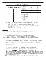
11
Time
Delay to
Deactivate
Relay or
Binary Pulse
1000000001
- +
RELAY_TURN_OFF_DELAY
1 – indicates current
value relative to
maximum delay
(MAX_DELAY)
Time delay from when flow measurement
is greater/less than relay switch point, to
turn off relay. Increments and decrements
in 1 second steps [max. default setting 10
seconds when using buttons].*
12
Alarm
Simulation
1100000001
- +
0000011111= output
“max”
1111100000= output
“min”
Alarm simulation mode. Pressing (+)
button forces maximum (corresponds
to A_OUT_DAC_COUNT_100) 4-20 mA
output. Pressing (–) button forces
minimum (corresponds to A_OUT_DAC_
COUNT_0) 4-20 mA output.
Relay output follows the RELAY_POLAR
setting.
14
Filter Setting
1111000001
- +
INPUT_FILTER_COUNT
LED 1 on = setting 3
LEDs 1-3 on = 18
LEDs 1-5 on = 30
LEDs 1-7 on = 50
LEDs 1-10 on = 100
Input filtering count: Default = 18.
(–) decreases filter, min. = 3.
(+) increases filter, max. = 100.
Filter value 18 reduces response
time <2 sec
Table 7 – Button Controls (continued)
* Maximum time delay is up to 65,000 seconds when using RS232 command line or PC interface.

