FCI Electronics
Manual Part No. 415988-001
Issued: (03/12/99)
Page 12 of 18
Rev. 05/18/06 EC V06-0481
Revision C
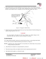
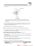
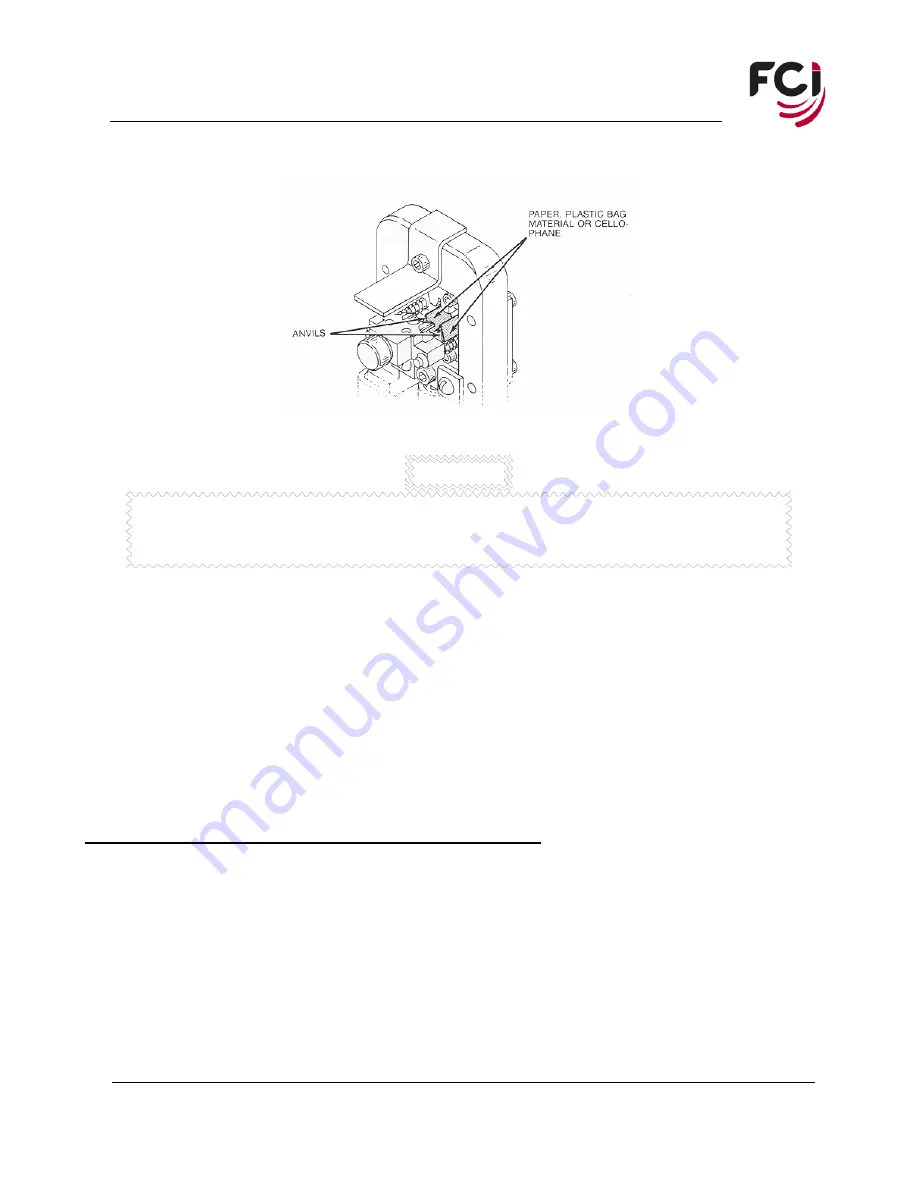
4. Cut out two strips of protective material. Then fold the strips in half and place them over the anvils
(see Figure 11).
Figure 11
WARNING
A pinch point exists between the hand tool's spring retainer and terminal holder (see
Figure 6). To prevent injury, always keep your fingers clear of this area when operating
the hand tool.
4. Slowly close the hand tool all the way. Next, using the 3/32-inch Allen wrench or a 1/16-inch
diameter pin, rotate the adjusting collar clockwise until the anvils just make contact with the
crimpers. Then tighten the anvil cap screw(s).
5. Open the hand tool and remove the protective covering from the anvils.
NOTE:
The adjusting collar remains unlocked for further adjustment of the crimp height.
6.
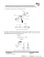
Crimp a terminal to the proper size wire. Then inspect the terminal and measure the wire barrel
crimp height as described in Section II, paragraph B.
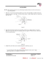
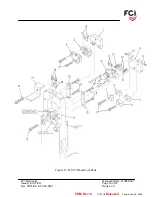
Wire and Insulation Barrel Crimpers and Tonker Removal
(See Figure 15)
1. Loosen but do not remove at this time, the two 4-40 cap screws (9) that secure the crimpers to the
crimper holder (1).
2. Remove the 6-40 cap screw (13) from the crimper holder (1). Then remove the spring retainer (21)
and the crimper holder (1) with crimpers attached.
3. Remove the two-tonker spring’s (19) and the two springs guide’s (20) from the hand tool frame.
This can be accomplished by tilting the hand tool down.
4. Remove the two 4-40 cap screws (9) that secure the crimper holder (1).
PDM: Rev:C Released .
STATUS: Printed: Feb 09, 2009


