Page 13 of 91
Rev. 4.20
MUDULO
EX-MEI/O
MUDULO
EX-MEI/O
SHORT CIRCUIT
ISOLATOR
MODULE
ISOLATOR
MODULE
MUDULO
EX-MEI/O
MUDULO
EX-MEI/O
ISOLATOR
MODULE
ISOLATOR
MODULE
INTERRUPTED
LINE
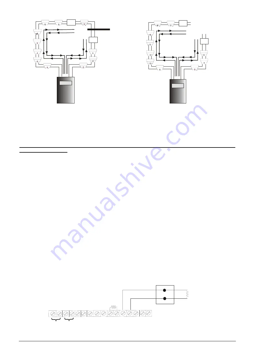
The installation of a detection circuit is made connecting all the control devices so that one closet ring is obtained.
As regards the conformity of the system to the rules UNI 9795 and EN 54-2, it is necessary to insert at least a
module isolator every 32 detectors or buttons. One can install up to a maximum of seven modules isolators for
each loop.
The connection uses the clips A-/ A+ for the installation output and B-/ B+ for the return of the same one.
The cable shielding (shielded) is connected only the part of starting to the clip SHI. The shielded of arrival
must not be connected.
•
Start from +1A and arrive at +1B, start from –1A and arrive at –1B.
•
Connect the cable shielding (SHI) of the starting part to the clip SHI. The arrival shielded must not be
connected.
•
If a loop is not used it is necessary to short circuit it with the jumper (-A with –B and +A with +B).
In case a short circuit on the line is produced, the part of circuit interested by the fault and included between the
two modules isolator will be disconnected, with the consequent loss of communication of a maximum of 32
elements (maximum number of elements that the rule UNI 9795 allows to lose in case of line short circuit). In case
of single interruption of loop, the control panel will be able to communicate from the two sides (output and return)
without losing the communication with the other installed elements.
Both the short circuit and the line interruption produce a fault restorable only to executed repair.
2.5.2 Fire alarm siren output
The clips of siren output are identified with the initials S+ and S-.
Each output is supervised for different faults of short circuit or open circuit. It is necessary to connect a 5.6 K• -
1/4 watt resistance of end of line on the last siren of the line. In order to ensure a most accurate supervision, the
siren must be connected to a dedicated line with a terminal resistance. One should not make several lines which
carry also as many terminal resistances, this could result in an incorrect functioning.
In the picture below an example of connection of two sirens.
As regards the maximum supplied current from each output, see page 90.
It is always advised to use fireproof shielded and twisted cable.
SIREN
5.6 Kohm 1/4W
5.6 Kohm 1/4W
-2
4
+
24
S
H
I
+
S
-S
- +
FAULT
S
H
I
O
C
1
O
C
2
O
C
3
O
C
4
RL2
RL1


