- 15 -
3.3 Interface
P
ort
An interface port (9-pin D-sub) is provided on the rear of the UPS to take
out the following signals. Use as needed.
CN1 (standard monitoring
interface)
D-sub 9-pin male
port (3 mm threads)
Pin No. Signal type Signal name
Description
1-4
“Opens” on
action
1-6
“Closes” on
action
UPS
failure signal
No-voltage contact signal due to a failure
in the UPS, a battery malfunction, or it is
time for battery replacement.
2-5
“Opens” on
action
2-7
“Closes” on
action
Input power
supply
abnormal
signal
No-voltage contact signal due to a
voltage error in the power supply (If the
power failure lasts up to 1.5 seconds,
there is no operation).
3-9
“Opens” on
action
3-8
“Closes” on
action
Battery
voltage drop
signal
No-voltage contact signal at
approximately 2 minutes before the end
of battery discharge (at rated load)
during battery operation.
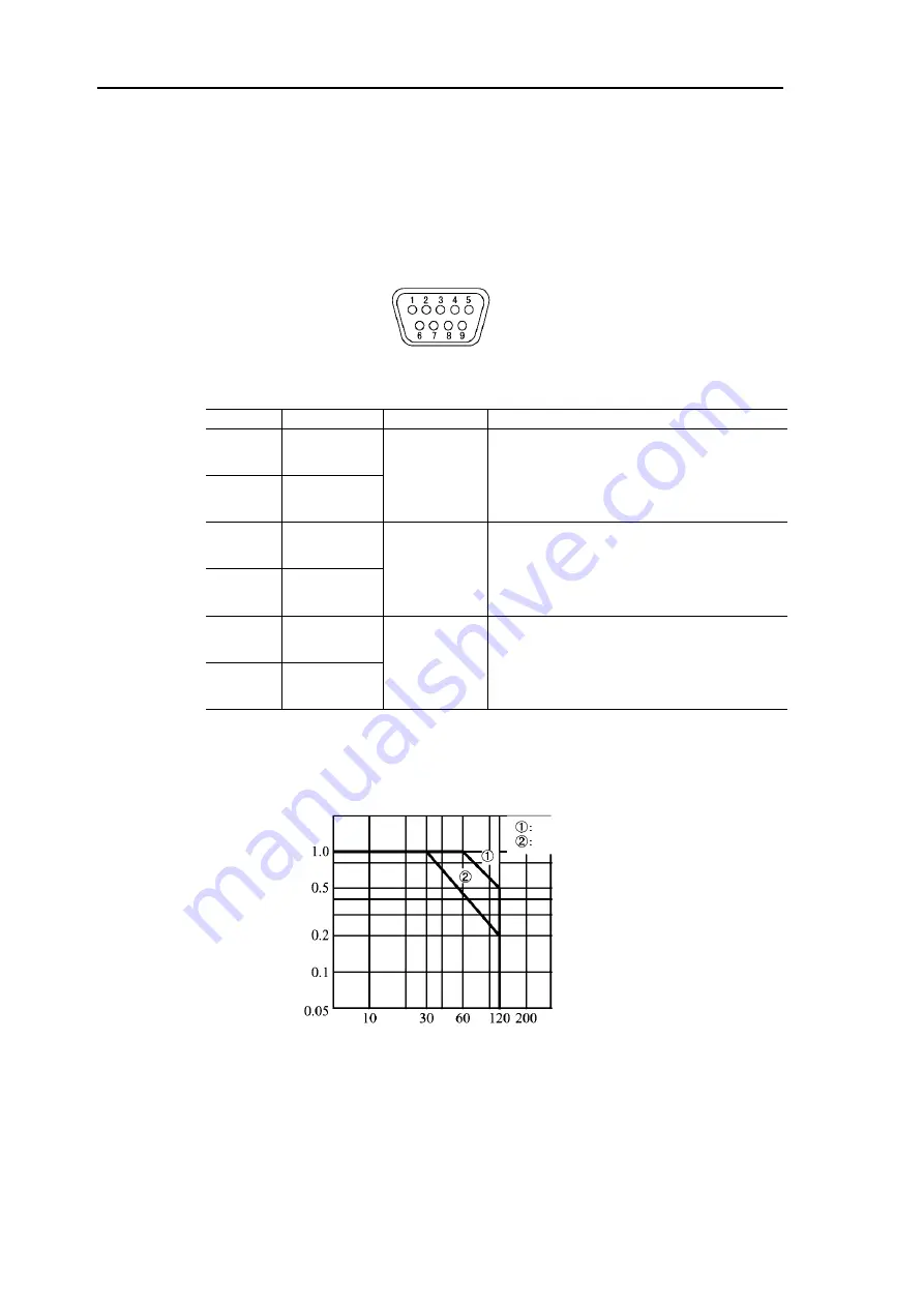
Use the contact output within the voltage and current ranges shown below.
AC contact rating
DC contact rating
Contact
current
(A)
Contact voltage [V]


