- 11 -
Connect remote refrigeration lines and condensate evaporator drain.
1. Remove the rear refrigeration line cover by removing the (4) screws on each end of base and the
(3) screws from under the rear frame channel.
2. Connect remote refrigeration lines through the 2-1/2” hole in counter as described in the Remote
Connection section in this manual.
3. Connect the provided condensate evaporator drain hose through the 2-1/2” hole in counter by
pushing it onto the drain fitting and secure it with provided hose clamp. Run the hose to a floor drain
or a remote condensate evaporator pan.
Refrigerated CRB Remote Models:
Cabinet Preparation
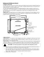
The CRB Remote models have a large condensate evaporator compartment hanging from the bottom of
case that contains the condensate evaporator pan. This compartment hangs inside the cabinet compartment.
The interior of the cabinet must be open to allow space for this compartment. The countertop must be cut to
allow the case’s base and condenser compartment to drop into the cabinet interior. Use the diagram below
for cutout dimensions.
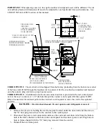
IMPORTANT:
When placing cases in a line up the number of end panels used will be different. The cut
out and hole placement dimension will need to be adjusted for each particular line up circumstance. See
LINE UP INTALLATION section of this manual.
The condensate air louvers are located on each side of the condensate evaporator compartment. Do not
block these louvers. The louver panel provided with case must be installed in the cabinet to allow
condensate moisture to vent. The louver can be placed on any side of cabinet, but must be as near to the top
as possible. A 6” minimum clearance must be maintained from cabinet louver.
Also (2) ½”dia. case fastening holes will need to be drilled through the counter top surface to attach case to
counter with ¼” X 2” screws provided. Use the diagram below for hole placement location.
IMPORTANT:
When placing cases in a line up the number of end panels used will be different. The cut
out and hole placement dimension will need to be adjusted for each particular line up circumstance. See
LINE UP INTALLATION section of this manual
TOP CUT
OUT
CASE TOP VIEW
3/4" END
PANELS
(2) 1/2" DIA
MTG. HOLES
CORD LOCATION
STANDARD OPT.1
FRONT
11/16 DOOR HANDLE
CLEARANCE
3.03
26.9
1.1
36.0 (36 UNIT)
48.0 (48 UNIT)
33.5 (36 UNIT)
45.5 (48 UNIT)
29.0


