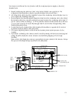
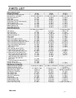
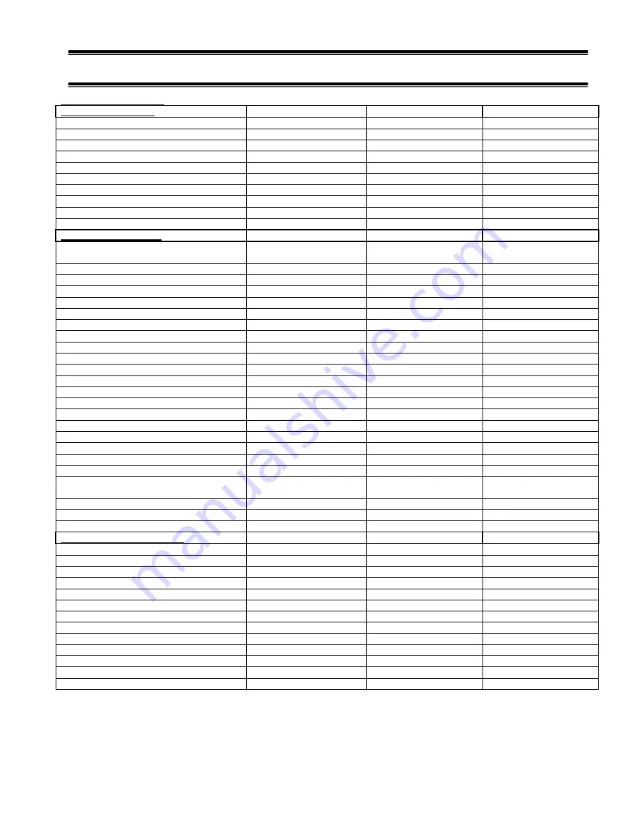
background image

IMSS E3265  


- 29 -


PARTS LIST 


REPLACEMENT PARTS 
Refrigeration System 
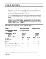
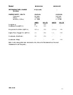
IMSS60 

IMSS84 

IMSS120 

Condensing Unit (Self Contained) 

30-19025 

30-19025 

30-19675 

Evaporator Coil   Left/ Right 

33-18811-L/33-18811-R 

33-19287-L/33-19287-R 

33-19647-L/33-19647-R 

Expansion Valve TXV 

32-19408 

32-19408 

32-19750 

Sight Glass 

32-54011 

32-54011 

32-54011 

Refrigerant Filter/Drier 

32-19067 

32-19067 

32-19067 

Refrigeration Solenoid Valve (Remote) 

32-19153 

32-19153 

32-19153 

Motor Evaporator Fan 

41-19070 

41-19070 

41-19070 

Wire Harness Evaporator Motor 

43-19083 

43-19083 

43-19735 

Blade Evaporator Fan  

72-12254 

72-11450 

72-12254 

Guard Evaporator Fan  

64-18015 

64-18015 

64-18015 

Electrical Components 


LED light bar 

42-19038 TOP/42-19038-

7 SHLF  

42-19038-3 

42-19038 SHLF/42-

19038-6 TOP 

Shelf Lamp Cord 

43-19061 

43-19061 

43-19061 

Shelf Lamp Socket 

43-19060 

43-19080-B 

43-19080-B 

Light power Supply 12V 

39-19039 

39-19039 

39-19039 

Power Switch 

41-13733 

41-13733 

41-19760 

Light Switch 

41-11066 

41-11066 

41-11066 

Temp Control (Before 5/23/12) 

32-19027 

32-19027 

32-19027 

Temp Control Display (Before 5/23/12) 

32-19092 

32-19092 

32-19092 

Temp Control Self Contained(After 5/23/12) 

32-19445-3 

32-19445-7 

32-19445-7 

Temp Control Remote (After 5/23/12) 

32-19445-3 

32-19445-71 

32-19445-71 

Temp Control Display (After 5/23/12) 

32-19446 

32-19446 

32-19446 

  Ribbon Cable display 

32-19093 

32-19093 

32-19093 

  Probe Temp 

32-19094 

32-19094 

32-19209 

Timer, Max Run (Before 5/23/12) 

41-17324 

41-17324 

  - 

Condensate Pan Ass'y (After 9/13) 

40-19996 

40-19996 

40-19997 

   Heater Condensate Pan ( (After 9/13) 

40-19996-1 

40-19996-1 

40-19997-1 

Condensate Pan Ass'y (Before 9/13) 

SA4889 

SA4889 

SA5345 

   Heater Condensate Pan (Before 9/13) 

40-17861 

40-17861 

40-19392 

    Condensate evap pan (Before 9/13) 

47-15679 

47-15679 

M19107 

   HighTemp Safety Ass'y (Before 9/13) 

SA-1880 

SA-1880 

  - 

   Float Switch condensate Pan  
  (Before 9/13) 

41-13022 

41-13022 

  - 

   Float Condensate Pan (Before 9/13) 

SA2928-1 

SA2928-1 

  - 

Optional Power Cord 

43-19090 

43-19090 

  - 

Optional Condensate Pump 

47-18980 

47-18980 

47-18980 

Miscellaneous Components 


Display Deck Plastic Left/Right 

15-18856-L/ 15-18856-R 

15-19292-L/ 15-19292-R 

15-19292-L/ 15-19292-R 

Display Deck Plastic Center 

    - 

     - 

15-19720 

Fastener Pad Set Display Deck 

77-17848/77-17849 

77-17848/77-17849 

77-17848/77-17849 

Metal Shelf  Assy w/light 

SA5397-2 

SA5397-1 

SA5399-1L/SA5399-1R 

Air Diffuser Air Discharge 

W11533-1 

W11533-5 

W11533-7 

Shelf Bracket Long 

67-18727 

67-18727 

67-18727 

Shelf Bracket Short 

67-18727-1 

67-18727-1 

67-18727-1 

Clip Shelf Cord Retainer 

81-30618 

81-30618 

81-30618 

Thermometer 

32-13662 

32-13662 

32-13662 

Straight Deflector End 

15-19729-1 

15-19729-1 

15-19729-1 

Straight Deflector Side 

15-19730-4 

15-19730-2 

15-19730-1 

Acrylic Air Deflector Seal 

64-19773 

64-19773-1 

64-19773-2 

Acrylic Deck Product Stop 

15-19863-1 

15-19863-3 

15-19863-3/15-19863-5 


Summary of Contents for IMSS84 Series

Page 1: ...MSS120 MODELS INSTALLATION OPERATIONS MANUAL KEEP THIS MANUAL FOR FUTURE REFERENCE Engineering and technical data are subject to change without notice FEDERAL INDUSTRIES P O Box 290 Belleville WI 5350...

Page 2: ...COMPONENT LAYOUT IMSS120 11 CONDENSATE EVAPORATOR 12 CONDENSATE PUMP 12 SHELVES 13 14 OPERATING INSTRUCTIONS 15 USER CONTROLS 15 POWER SWITCH 15 LIGHT SWITCH 15 ELECTRONIC CONTROL 15 INITIAL START UP...

Page 3: ...nts contain technical instructions are intended only for persons qualified to perform electrical work DANGER Improper or faulty hookup of electrical components in the case can result in severe injury...

Page 4: ...occur if you ignore the message WARNING Severe injury or death can occur if you ignore the message CAUTION Minor injury or damage to your case can occur if you ignore the message NOTICE This is impor...

Page 5: ...ons such as near cases with water misting or fogging devices Failure to locate this case as stated will reduce the performance of your Island display and will affect temperature of interior of case an...

Page 6: ...rements of the case See the electrical data plate located on the rear exterior of the case for the proper circuit size for each case The cord is factory installed protruding from the corner of the cas...

Page 7: ...proper drainage of defrost water to the condensate pump A wrench is included to aid in adjusting leg levelers Check the level of the case where the display overhangs the base Adjust the 4 outside leg...

Page 8: ...er screws from top of panel The screws will stay on the panel even after they are detached from base 2 Tilt the top of the panel away from the base and pull up on panel to allow the side panel tabs to...

Page 9: ...tay on the panel even after they are detached from base 2 Tilt the top of the panel away from the base and pull up on panel to allow the side panel tabs to pull out of the side panel slots 3 Set the p...

Page 10: ...5 1 4 2 Base Component Layout Remote IMSS60 IMSS84 CONTROL PANEL LOCATION CONDENSATE PUMP REMOTE REFRIGERATION LINE ACCESS COVER LIGHT POWER SUPPLY QUANITY MAY DIFFER POWER CONNECTION BOX ELECTRICAL B...

Page 11: ...Y WIRING DIAGRAM 120 41 40 41 4 3 3 0 3 0 4 3 Base Component Layout Remote IMSS60 IMSS84 REMOTE REFRIGERATION LINE ACCESS COVER 3 8 HIGH PRESS CONNECTION REFRIGERATION SHUT OFF SOLENOID VALVE SIGHT GL...

Page 12: ...pacity is available a high wattage heater is used The heater turns off automatically when the water level in the pan drops Check that the float is positioned correctly and that the switch operates at...

Page 13: ...lace the additional shelf brackets in the same height level on the opposite end of case The 2 short brackets must go on the short end and 2 long brackets must go on the long end The short bracket with...

Page 14: ...the socket is not being used for a shelf light the cap must be plugged into socket to prevent contamination and moisture out of the socket 7 Plug in each shelf light by aligning the male pins on the...

Page 15: ...e WARM setting is an Off position this position turns the refrigeration off and all indicator lights will also be off at this setting ON The control will be on from the warmest setting at 1 and the co...

Page 16: ...ntire shelving area Determine desired shelving location before placing product in case Product must be removed to readjust shelf location Allow a minimum of 2 between top of product and bottom of shel...

Page 17: ...ondenser coil will void condenser warranty This procedure is for Self Contained models The remote condenser coil must also be cleaned at same intervals 1 Disconnect power to the unit 2 On IMSS60 and I...

Page 18: ...t electrical damage to the case NOTICE Shut off lights and power switches and remove all products from case Allow sufficient time for the unit to reach room temperature before proceeding with cleaning...

Page 19: ...hazing and yellowing of material Note Detergents are not recommended and do not use abrasive cleaners or pads to prevent scratching of surfaces SHELVES 4 DISPLAY DECK FAN SHROUD FAN SHROUD FAN SHROUD...

Page 20: ...sembly do not rinse or submerge fan motors 9 Clean the entire interior of the case using warm soapy water Wipe off all soapy water with a damp cloth and allow to dry DO NOT use solvents such as Aceton...

Page 21: ...ocked evaporator coil Check that paper or foreign materials are not blocking evaporator If the evaporator coil is blocked due to excessive frost put into manual defrost Excessive frost can buildup ove...

Page 22: ...ase has a receiver tank large enough to hold all the charge you maybe able to pump down the system when service is required If moisture or liquid is observed around or under a Federal Industries case...

Page 23: ...tries case you should evacuate the refrigerant charge before shipment Federal Industries recommends that the charge be evacuated into a recovery system to prevent the possibility of HCFC s from being...

Page 24: ...Phase Number of Wires 2 GND 2 GND AMPS VOLTS AMPS VOLTS Compressor 12 230 Condenser Fan QTY 2 5 ea 230 Evaporator Fan Motor QTY 6 0 15 ea 230 0 15 ea 230 Lights Power Supply 12v QTY 4 1 6 230 1 6 230...

Page 25: ...unit Do not move or relocate this sensor The coil sensor is strapped to the evaporator coil This sensor location is critical for proper operation of the unit Do not move or relocate this sensor The t...

Page 26: ...troller Operation Temperature Units Fahrenheit F 4 Defrost Termination Method Evaporator Sensor Evaporator Sensor SET POINTS 8 Cut In Warm 14 F 41 F 9 Cut Out Warm 4 F 28 F 10 Cut In Cold 2 F 41 F 11...

Page 27: ...y the Electronic control and timers outlined in the control section of this manual Note The condenser fan runs continuously Remote Models Use pressure gauges to set pressure control Refrigeration R404...

Page 28: ...used to flow through tubing while brazing refrigeration lines 4 Suction line must be insulated the entire length with Armaflex or equivalent Do not run liquid line inside insulation with suction line...

Page 29: ...32 19446 Ribbon Cable display 32 19093 32 19093 32 19093 Probe Temp 32 19094 32 19094 32 19209 Timer Max Run Before 5 23 12 41 17324 41 17324 Condensate Pan Ass y After 9 13 40 19996 40 19996 40 1999...

Page 30: ...3 R 12 B 22 G 24 G 25 B 17 B 16 R 15 R 14 Y 10 Y 9 R 2 B 1 R 4 B 3 R 20 L2 L1 N B R B BL R BL SHELF LAMP B B BL B B R B BL R BL SHELF LAMP B B BL B B R B BL R BL SHELF LAMP B B BL B POWER SUPPLY B R B...

Page 31: ...Y 21 R 11 R 23 B 5 B 13 R 12 B 22 G 24 G 25 B 17 B 16 R 15 R 14 Y 10 Y 9 R 2 B 1 R 4 B 3 R 20 L2 L1 N B R B BL R BL SHELF LAMP B B BL B B R B BL R BL SHELF LAMP B B BL B B R B BL R BL SHELF LAMP B B...

Page 32: ...BL TOP LAMP B B R B BL TOP LAMP B TURN FULL CLOCK WISE 208 240V 60Hz 1PH Y 6 R 15 3 2 4 1 MAX RUN TIMER TURN FULL CLOCK WISE RIBBON CABLE G 26 1 2 3 4 5 6 7 8 9 10 11 RIB RIB TERM BLOCK TEMP PROBE PB...

Page 33: ...D W WHITE Y YELLOW BL BLUE COLOR CODE BRW BRW BL BL B BL B BL B B B R B R JUMP R Y TURN FULL CLOCK WISE 208 240V 60Hz 1PH Y 6 R 15 3 2 4 1 MAX RUN TIMER TURN FULL CLOCK WISE RIBBON CABLE G 26 1 2 3 4...

Page 34: ...0 R 2 B 1 R 4 B 3 L2 L1 N B R B BL R BL SHELF LAMP B B BL B B R B BL R BL SHELF LAMP B B BL B B R B BL R BL SHELF LAMP B B BL B POWER SUPPLY B R B BL R BL SHELF LAMP B B BL B B R B BL R BL SHELF LAMP...

Page 35: ...G 24 G 25 B 17 B 16 R 15 R 14 Y 10 R 2 B 1 R 4 B 3 L2 L1 N B R B BL R BL SHELF LAMP B B BL B B R B BL R BL SHELF LAMP B B BL B B R B BL R BL SHELF LAMP B B BL B POWER SUPPLY B R B BL R BL SHELF LAMP...

Page 36: ...G GREEN DEFROST PROBE IMSS120 SELF CONTAINED 91 19739 9 3 12 B BR G B R B BL R BL SHELF LAMP B B BL B B R B BL R BL SHELF LAMP B B BL B B R B BL R BL SHELF LAMP B B BL B B BL B B R TOP LAMP B BL B L1...

Page 37: ...B B B R B R B BL TOP LAMP B B R B BL TOP LAMP B B R B BL TOP LAMP B 208 240V 60Hz 1PH Y 6 R 15 RIBBON CABLE G 26 1 2 3 4 5 6 7 8 9 10 11 RIB RIB TERM BLOCK TEMP PROBE PB1 DEFROST PROBE PB2 POWER SWIT...

Page 38: ...PLY BRW BL B R G GREEN B BLACK R RED W WHITE Y YELLOW BL BLUE COLOR CODE BRW BRW BL BL B BL B BL B B B R B R JUMP R Y 208 240V 60Hz 1PH Y 6 R 15 RIBBON CABLE G 26 1 2 3 4 5 6 7 8 9 10 11 RIB RIB TERM...

Page 39: ...TE 91 19740 9 3 12 B BR G B R B BL R BL SHELF LAMP B B BL B B R B BL R BL SHELF LAMP B B BL B B R B BL R BL SHELF LAMP B B BL B B BL B B R TOP LAMP B BL B L1 L2 N LIGHT SWITCH B R G BLK R R BLK Y R BL...

Reviews: