Summary of Contents for USD

Page 1: ...E R A L P I O N E E R OVERCURRENT TRIP UNIT TYPE USD March 1982 C 3 217 2 INSTRUCTION MANUAL FEDERAL PIONEER LIMITED OVERCURRENT TRIP UNIT TYPE USD Prepared by Dated Typed by Charles Ho March 1982 dm...

Page 2: ...4 Courtesy of NationalSwitchgear com...

Page 3: ...ts Ground Fault Element The ZSIP Functions Selecting Settings 3 2 3 3 3 4 3 5 4 Specifications 5 Scope Current Sensor Relay Configurations Long Time Element Short Time Element Instantaneous Element Gr...

Page 4: ...3 fc Courtesy of NationalSwitchgear com...

Page 5: ...den USD_Relav Jrao dance Burden Overcurrent Trip System Connections Remote Indication and ZSIP Connections Remote Indication and ZSIP Connections Remote Indication and ZSIP Connections Test Connection...

Page 6: ...1I L Courtesy of NationalSwitchgear com...

Page 7: ...nd for the provision for trip energy are semiconductors capacitors transformers etc Thus except for the shunt trip and the mechanical relay contacts for remote fault indication the trip is completely...

Page 8: ...ication and the ZSIP is accomplished by means of a colour coded wiring harness The wiring harness is attached to a 10 pin connector that plugs and locks into the side of the relay enclosure 2 4 Shunt...

Page 9: ...t of the three phase primary current is compared to preset values in each of the three elements If it does not exceed any of the preset pickup levels the relay continues to monitor the system If the c...

Page 10: ...n its zone proceeds to trip immediately It also sends a restraint signal to the upstream trip devices and causes them to revert to their time coordinated protection mode Therefore instantaneous protec...

Page 11: ...IP ST TCP Time Coordinated Protection means that there is ZSIP on the ground fault element only and the short time element is self restrained The third position marked TCP means that both ground fault...

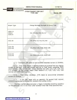
Page 12: ...t rime delays of 2 4 6 8 10 14 16 22 26 and 30 seconds at 600 al current 50 60Hz Time Delay Tolerance 10 based on symmetrical sinusoidal current rt Time Element Pickup settings available 2X 3X 4X 6X 8...

Page 13: ...han 0 04X the sensor tap setting If the breaker closes and the current is greater than 0 04X but less than 13X the sensor tap setting the discriminator monitors the current for 40 milliseconds and if...

Page 14: ...rse at low fault levels and become definite at fault levels exceeding 500 rated current The definite time delays provided are 0 08 0 14 0 20 0 26 and 0 32 seconds In the inverse region these become 0...

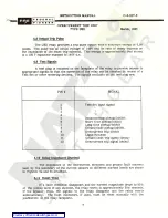
Page 15: ...NAL Test Set input signal t 1 2 3 4 Instantaneous pickup inhibit Short time pickup inhibit Long time pickup inhibit Ground fault pickup inhibit Overcurrent trip inhibit Logie common Ground fault trip...

Page 16: ...5 5 1 Secondary Injection Testing of the overcurrent trip system with secondary injection is easily accomplished under field conditions with the Federal Pioneer portable Test Set Type DDT USD The tes...

Page 17: ...be as short as possible otherwise current capability will be limited and only minimum testing achieved 5 2 6 Before attempting testing the USD relay the element and setting to be tested must be decide...

Page 18: ...anual C 3 233 5 2 16 Care should be taken when using magnetic pickup devices for measuring current eg clip on ammeters current sensors etc to ensure that the readings are not being influenced by the s...

Page 19: ...ing Refer to the circuit breaker instruction manual for mechanical mounting details b Ensure that an overload or short circuit does not exist in the load circuit c Check that there is no ground curren...

Page 20: ...1982 Also the condition under which improper etting or settings must be noted iperation was noted ie during initial testing during maintenance etc and the type jf testing equipment used This will ena...

Page 21: ...W G Z w o R R A E N C S T F I O F R I M E E R R S 25 a H BYPASS DLY IF NO RESTRAINT cn CO N 2 H LOGIC POWER SUPPLY O 00 po r MONITOR TRIP PASS o T3 l C a o a 2 G F TIME DELAY r B a r G F MONITOR a G F...

Page 22: ...0 11 o E D o T o 1 S 25 E 0 T O I T 2 O L 2 33 3 O M o 5 A o 3 8 45 E o P Y O O I 2 t T 0 9 O L 3A O 1 o u o o 6X P o u G I L 1 7 X 1 AJ o c if o 8 X 2 0 K N 9 X 3 LU u 4 1 0 X G v 2 2 P 5 9 1 1 X 0...

Page 23: ...45 P CO Y I2 t Q T 0 9 L U o 6X P O G o L i 7X o LLI c 0 2 8 X 0 G co 4 K N 3 9X u UJ 2 4 IOX G 2 P 5 9 I IX 0 N o 2 0 5 14 0 D T IB 4 0 6 16 0 E I 22 0 L 2 ao 7 6 M C A 8 26 0 3 8 0 10 E Y 10 0 9 30...

Page 24: ...1 iw A L ir HIH INK 1 t T r m i N m H r T r Tap Setting Amps Resistance Ohms Sensor Type I ill i n ITETJ 3T I mi C 50 C 70 C 100 C 150 060 095 165 220 mi rtn CSD 1 5 Tn 2 IF H t biHii 100 Tfjijir mi...

Page 25: ...DELAY AT 6 TIMES SENSOR TAP 100 100 imLY AVIA ikvr kU l s 90 90 P S 80 80 70 70 t 60 60 l 2 PICKUP AT 0 6 0 7 0 8 0 9 1 0 1 1 TIMES SENSOR TAP 50 50 Hkl Vkl klkU 40 40 ht 30 30 s 7 1 w r A S 7 20 20 i...

Page 26: ...lHtrhiJ t t r H44 L T tr 4 T TT T T s r r I I i r t 4 H44 r r T T t II 3 t i I I 1 r nn T i i ii ffr I r T r m 4 i i h Tit Tttt 44 B T T I Hi i i t T f 1 t I i It i T f 4 i 4 m t 44 4 r m 4r 4 f _ 1 L...

Page 27: ...A L P I O N E E R OVERCURRENT TRIP UNIT TYPE USD March 1982 1 1 Htt ft fr i i T if j r r i T U44 4 t f r I I I sr I T f PT 4 i 3 i r t FIG 5b INPUT IMPEDANCE OF SOLID STATE OVERCURRENT RELAY TYPE USD...

Page 28: ...STRAP C T TYPE USO OVERCURRENT RELAY CONNECTIONS WIRE PHASE C T AS SHOWN FOR JB JW OR J 4W SYSTEMS 5 OR V 0 FOR J jw FOR 3 4 W NEUTRAL T 2 OR TRIP COIL COIL Ti G r 4 N r Z i 1 1 if i L r r i i i it i...

Page 29: ...W MOV INSUL 105 CU ALL WlRE ARE LOOSE AMO 75 INCHES LONG 1 t 9 10 m u DO O O Q G O 2 4 0 0 N FRONT VIEW FIR NO COLOUR _ OE WIRES CONTROL POWER f 120 V MHz 2 5 VA L2 LI t GF L T OR i CONTACT RATING r...

Page 30: ...NECTOR HARNESS CATALOGUE MO U P H COLOUR COOCO 1 GA WIRES TYPE TEW IMV IMSUL WW ALL WIRES ARE LOOS AMO 7S INCHES LONG i c i 1 i T 0 3 0 0 0 3 2 4 t i ie FRONT VIEW FIN MO COLOUR OF WIRES ZSIP RESTRAIN...

Page 31: ...H COLOUR COOE D 1 GA WIRES TYPE TEW 00 V INSUL MS CU ALL WIRES ARE LOOSE AND TS INCHES LONG tc I V_ V ca 9 5 K o 1 3 S 3 s o o o o 1 00 30 3 2 4 II tO FRONT VIEW PIN NO COLOUR _ Of WIRES CONTROL POWER...

Page 32: ...ESTS Ai 1 I 1 I I I B C A A A A CONTROL CONTACTS y ALLOCATED AT THE REAR s OF THE BREAKER fa fa fa i GN i GN rGN Pc P o C TC UK 0 T2 o QTI CURRENT SENSORS SG GN SN USD 6 W S C BL SB R S A iCONTROL PLU...

Page 33: ...30HL 3 30H 3 30HL 3 50H 3 50HL 3 50H 3 50HL 3 600A 800A 1600A 2000A CSD 8 400 600 800 800A 1600A 2000A 30H 3 30HL 3 50H 3 50HL 3 50H 3 50HL 3 CSD 16 1000 1200 1600 50H 3 50HL 3 50H 3 50HL 3 1600A 2000...

Page 34: ...RACTERISTIC MODELS USD 3 USD 3IR X X X LONG TIME X SHORT TIME WITHOUT ZSIP X X INSTANTANEOUS X X X X GROUND FAULT WITH ZSIP X X LOCAL AND REMOTE INDICATION X X Add the following suffixes 16 for use wi...

Reviews: