Chapter 4: Wiring the INTEGRITY Lightbar in the Vehicle
14
Integrity Lightbar
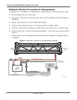
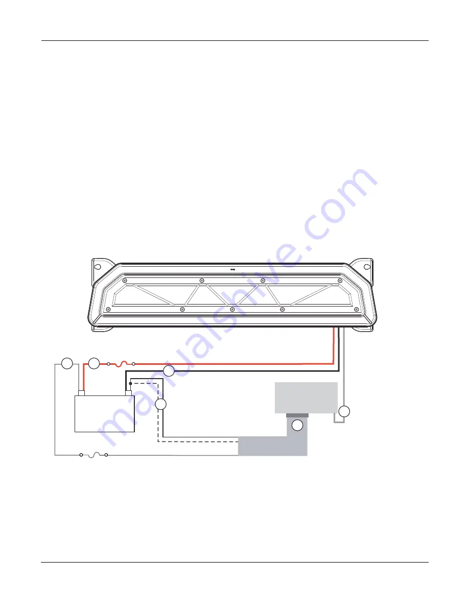
Making the Electrical Connections for Reprogramming
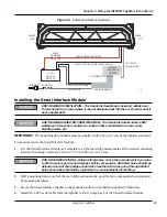
To supply power to the lightbar, use a fully-charged 12-volt automotive battery and follow these steps:
1.
Place the lightbar on a sturdy, flat surface.
2.
See Figure 3.1. Plug the CAT5 communication cable (1) from the lightbar into the Serial Interface
Module (J1).
3.
Plug the 24-pin harness (2) into the Serial Interface Module.
4.
Attach the black ground-power line (3) to the negative battery (–GND) terminal.
5.
Attach the red power line (4) through a 40 A Maxi™ fuse to the positive battery (+BAT) terminal.
6.
Attach the white wire (5) from the 24-pin harness through a 1 A fuse to the positive battery (+BAT)
terminal.
7.
Attach the black wire and the black/white wire (6) from the 24-pin harness to the negative battery
(–GND) lug.
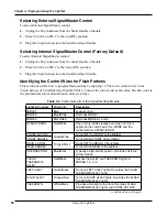
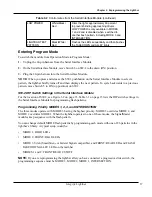
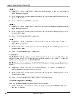
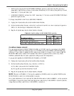
Figure 3.1 Electrical connections for reprogramming the lightbar
SERIAL
INTERFACE
MODULE
POWER LINE (RED)
GROUND POWER LINE (BLACK)
BLACK WIRE
BLACK / WHITE WIRE
WHITE WIRE
24-PIN HARNESS
5
290A7448
+
–
12 Vdc
VEHICLE
BATTERY
4
3
1
2
6
FUSE
1 A
FUSE
40 A MAXI
PASSENGER
SIDE
DRIVER
SIDE
CAT5 COM.
CABLE (GRAY)
Summary of Contents for Integrity44
Page 2: ...blank page ...


