Chapter 3: Reprogramming the Lightbar
15
Integrity Lightbar
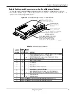
Switch Settings and Connectors on the Serial Interface Module
The switches to select flash patterns and lightbar functions are accessible throughon the PCB on the
Serial Interface Module. Figure 3.2 shows the locations of the switches and connectors. See Table 3.1 for
a desciption of switch settings and functions.
Figure 3.2 DIP switch settings in Serial Interface Module
J3 CONNECTOR FOR
SERIAL CABLE FROM
LIGHTBAR
J1 CONNECTOR FOR 24-CONDUCTOR
CABLE SUPPLIED WITH SERIAL
INTERFACE MODULE
SW2 DIP SWITCHES (SEE
TABLE 3.2 ON PAGE 16)
PROGRAMMING HEADER FOR CLONING
FLASH PATTERNS FROM VEHICLE TO
VEHICLE. (SEE THE INSTRUCTIONS
INCLUDED WITH THE PROGRAMMER.)
SW1 PUSHBUTTON FOR
SELECTING FLASH PATTERNS
290A7703
Table 3.1 SW-2 DIP Switch Settings
SW-2
Switch
Number
Switch Setting
Function
Up
(OFF)
Down
(ON)
1
✔
FRONT/REAR LEDs cut off (turn off) when 12 Vdc is applied
their control wires (Table 3.2 on page 16).
1
✔
FRONT/REAR LEDs enable (turn on) when 12 Vdc is
applied to their control wires
2
✔
Keep in OFF position
3
3
✔
✔
Intersection
Scene light
4
✔
SignalMaster, External controller
4
✔
SignalMaster, Internal controller
5
✔
Cycle forward through the selection of flash patterns
5
✔
Cycle backward through the selection of flash patterns
6
✔
Operation Mode
6
✔
Program Mode
7
Switch for INTERSECTION operational settings (Table 3.3 on 19)
8
Switch for INTERSECTION operational settings (Table 3.3)
Summary of Contents for Integrity44
Page 2: ...blank page ...


