16
Chapter 3: Reprogramming the Lightbar
16
Integrity Lightbar
Selecting External SignalMaster Control
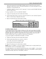
To select External SignalMaster control:
1.
Unplug the 24-pin harness from the Serial Interface Module.
2.
Move Switch 4 on SW-2 to the up (OFF) position.
3.
Plug the 24-pin harness into the Serial Interface Module.
Selecting Internal SignalMaster Control (Factory Default)
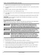
To select Internal SignalMaster control:
1.
Unplug the 24-pin harness from the Serial Interface Module.
2.
Move Switch 4 on SW-2 to the down (ON) position.
3.
Plug the 24-pin harness into the Serial Interface Module.
Identifying the Control Wires for Flash Patterns
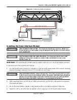
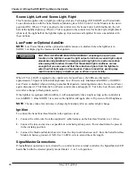
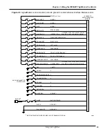
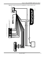
This section describes how to program flash patterns by applying 12 Vdc to the control wires in the
24-pin harness of Serial Interface Module. Table 3.2 shows the control wires and colors. The first color is
the predominant color and additional colors are stripes.
Table 3.2 Control wires from the Serial Interface Module
Lightbar Controls
Wire Color
Description
MODE 1
Blue
Lowest priority
MODE 2
Blue/White
Overrides MODE 1
MODE 3
Black/Red
Overrides MODES 1 and 2
STEADY BURN
Red/White
One or more LEDs steadily burn when 12 Vdc is
applied to the control wire for a MODE and the
control wire for STEADY BURN
FRONT CUTOFF
Green/White
Turns OFF the FRONT of the lightbar
FRONT ENABLE
Turns ON the FRONT of the lightbar
REAR CUTOFF
Orange/Black
Turns OFF the REAR of the lightbar
REAR ENABLE
Turns ON the REAR of the lightbar
INTERSECTION
Blue/Black
Typically a high-activity pattern. Overrides all three
priority modes.
FLASH
TAKEDOWN/
ALLEY
Red/Black
Flashes the ALLEY and TAKEDOWN lights in
MODES 1, 2, or 3
LEFT ALLEY
Green/Black
Turns on LEFT ALLEY lights. Overrides the FLASH
TAKEDOWN/ALLEY lights
RIGHT ALLEY
Orange/Red
Turns on RIGHT ALLEY lights. Overrides the FLASH
TAKEDOWN/ALLEY lights.
TAKEDOWN
White/Black
Provides white light to the front. Overrides FLASH
TAKEDOWN/ALLEY lights and FRONT CUTOFF.
(continued on next page)
Summary of Contents for Integrity44
Page 2: ...blank page ...


