Chapter 4: Wiring the INTEGRITY Lightbar in the Vehicle
23
Integrity Lightbar
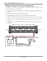
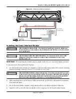
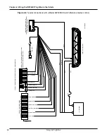
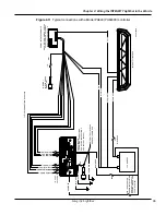
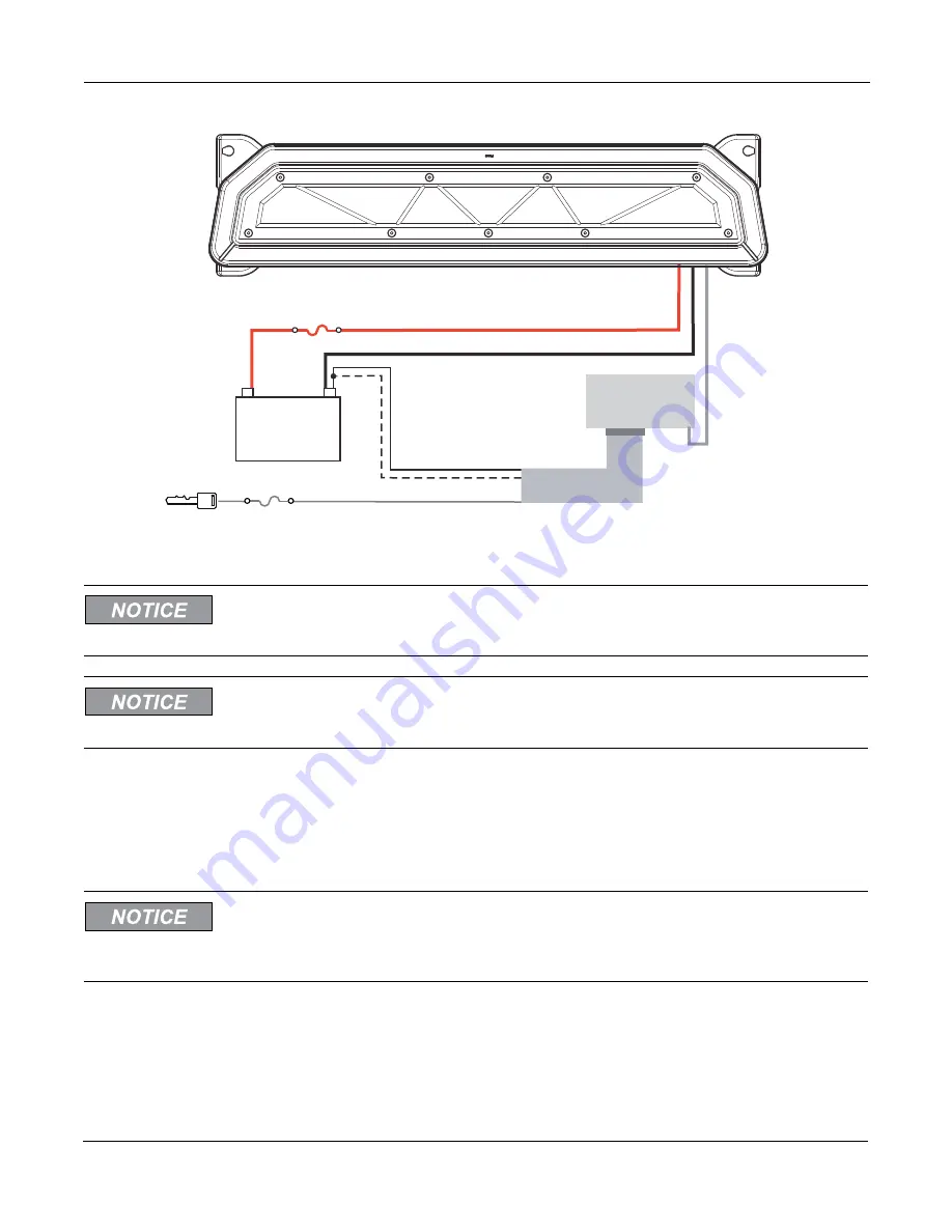
Figure 4.1 Power and cable connections
SERIAL
INTERFACE
MODULE
(+BAT) POWER LINE (RED)
(NEG-) GROUND POWER LINE (BLACK)
J1 CONNECTOR
BLACK / WHITE WIRE
CAT5 COM.
CABLE (GRAY)
WHITE WIRE
24-PIN HARNESS
290A7447
+
–
12 Vdc
VEHICLE
BATTERY
FUSE (1 A)
FUSE
40 A MAXI
IGNITION
PASSENGER
SIDE
DRIVER
SIDE
Installing the Serial Interface Module
UNIT REQUIRES VENTILATION—The Serial Interface Module needs to radiate heat.
Do not install it in an area where it cannot dissipate heat into the air. Do not mount it
near a heater duct.
UNIT REQUIRES SHELTER FROM WEATHER—The Serial Interface Module is NOT
waterproof. It must be mounted in a location that is sheltered from rain, snow,
standing water, etc.
IMPORTANT:
The Serial Interface Module must be installed within 36 in (91 cm) of the lightbar controller.
To mount and wire the Serial Interface Module :
1.
Use the Serial Interface Module as a template to scribe four drill-position marks at the selected mounting
location. Mounting centers are 2.00 in x 5.95 in (5.08 cm x 15.11 cm).
DRILLING PRECAUTIONS—Before drilling holes, check the area into which you plan
to drill to ensure you do not damage vehicle components. All drilled holes should be
de-burred and all sharp edges should be smoothed. All wires going through drilled
holes should be protected by a grommet or convolute/split-loom tubing.
2.
Drill a mounting hole at each of the four drill-position marks, sized for the recommended user-supplied
#8 mounting hardware.
3.
Secure the Serial Interface Module to the mounting surface with installer-supplied #8 hardware.
4.
Install the CAT5 serial cable from the lightbar to the J3 output jack of the Serial Interface Module.
Summary of Contents for Integrity44
Page 2: ...blank page ...

