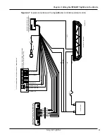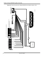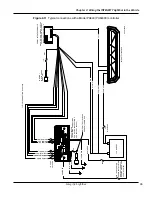
Chapter 4: Wiring the INTEGRITY Lightbar in the Vehicle
26
Integrity Lightbar
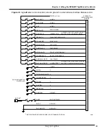
Scene Light, Left and Scene Light, Right
This function applies only to lightbars with SpectraLux
TM
Technology (INTEGRITY and Vision SLR).
To use this function with the Serial Interface Module, place SW-2 Switch 3 in the Module in the down
position (ON). When 12 Vdc is applied to the control wire for Scene Light, Left (blue/black), the left
half of the lightbar lights up. When 12 Vdc is applied to the control wire for Scene Light, Right (black/
white/red), the right half of the lightbar lights up. Intersection and Lightbar Test are unavailable with
these options.
Low Power or Optional AutoDim
NOTE:
Low Power Mode and the optional AutoDim feature are disabled when the lightbar is in
MODE 3 or displaying the Intersection flash pattern.
USE THE LOW POWER FUNCTION PROPERLY—Enabling the Low Power
function in the lightbar causes the light output to fall below current light output
standards and guidelines for emergency warning lights. Use extreme caution
when using this function. Ensure that the ambient light conditions are low
enough that you are seen and that the reduction of glare from the lightbar is
safer than full light output in the situation. Failure to heed this warning may
result in serious injury or death to you or others in your vicinity.
When 12 Vdc (+BAT) is applied to the control wire for Low Power, the LEDs are dimmed to
approximately 50 percent of their full brightness. Low Power is only functional in MODE 1 or MODE 2.
Low Power is disabled when switching to another flash pattern, including Intersection. To use Low Power
again, disconnect 12 Vdc from the Low Power control wire and reapply 12 Vdc to the Low Power control
wire after a change in flash pattern occurs.
If the lightbar is equipped with AutoDim, it will automatically dim at night as long as the controller is
not in MODE 3. Once MODE 3 is removed, the lightbar will again dim to 50 percent of full brightness.
NOTE:
The may take a few minutes to change light intensity after an ambient light change.
Ignition
To connect the Serial Interface Module to the ignition circuit:
1.
Connect the white wire from the supplied J1 cable harness on the Interface Module to a 1 A fuse.
2.
Connect the fuse end as close as possible to switched ignition power. Power should also be present
in the cranking position.
3.
Connect the black and black/white wire from the 24-pin cable harness on J1 from the Serial Interface
Module to battery ground (–GND). Use 16 AWG wire to extend the cable length.
SignalMaster Connections
If SignalMaster operation is not activated by a control head or external controller, the SignalMaster LED
heads flash with the selected priority mode (Mode 1, 2, or 3) of operation.
Summary of Contents for Integrity44
Page 2: ...blank page ...

