Chapter 4: Wiring the INTEGRITY Lightbar in the Vehicle
27
Integrity Lightbar
Internal SignalMaster (Factory Default)
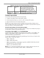
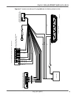
Internal operation uses the lightbar’s built-in SignalMaster controller to generate directional warning
patterns. With internal operation, an external SignalMaster controller is not needed. A standard low-
current switch box can activate the lightbar’s internal SignalMaster controller. To activate the lightbar’s
internal SignalMaster controller, apply 12 Vdc (+BAT) to the SignalMaster control wires
External SignalMaster
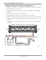
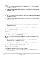
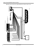
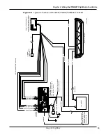
External operation uses the Serial Interface Module to drive each SignalMaster directional warning head
independently through an external Federal Signal SignalMaster controller or SS2000SM series siren
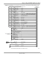
(Figures 4.3 through 4.6). Either device provides an independent ground signal to turn on each head.
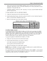
To cross reference external SignalMaster wiring to a Federal Signal controller or the SM2000SM series
siren, see Table 4.1.
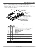
Table 4.1 Cross reference for controller leads (external Serial Interface Module control)
24-Pin Harness from
the Serial Interface
Module
S
ignal
M
aSter
* Wire
(Figure 4.2)
SS2000SM* Wire
(Figure 4.3)
Red
White
White (1)
Green
Brown
Brown (2)
Green/Black/White
Green
Green (3)
Orange/Green
Orange
Orange (4)
Orange
Purple
Purple (5)
Blue/Red
Gray
Gray (6)
Red/Green
Yellow
Yellow (7)
White/Red
Blue
Blue (8)
*Wire colors as described in the controller’s installation instructions.
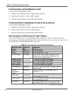
Figure 4.3 SignalMaster 331105 controller (external SignalMaster control)
WHITE
BROWN
GREEN
ORANGE
VIOLET
GRAY
YELLOW
BLUE
RED
GREEN
GREEN/BLACK/WHITE
ORANGE/GREEN
ORANGE
BLUE/RED
RED/GREEN
WHITE/RED
TO J1 ON
INTERFACE MODULE
290A7451
SIGNALMASTER CONTROLLER
331105 SHOWN
NOTE: FOLLOW THE
CONTROLLER’S INSTALLATION
INSTRUCTIONS FOR POWER,
GROUND, AND OTHER
POSSIBLE FUNCTIONS.
Summary of Contents for Integrity44
Page 2: ...blank page ...

